
Robot control circuit composed of transistor and NE555
The schematic diagram depicted in Figure 2-33 (a) outlines the operational mechanism of a robot designed for object detection and navigation. The primary function of this robot is to maintain forward motion until an obstacle is detected. The robot is equipped with sensors, typically ultrasonic or infrared, positioned at the front and sides to detect the presence of objects within its path.
When the sensors at the front of the robot do not detect any objects, the control system maintains a command for the motors to drive the robot forward. This movement is achieved through a differential drive mechanism, where two independent motors control the left and right wheels, allowing for precise movement and turning capabilities.
In scenarios where an object is detected on either side, the control system processes the sensor data to determine the appropriate response. If an object is detected on the left, the robot will initiate a right turn, and conversely, if an object is detected on the right, the robot will turn left. The turning action is executed by adjusting the speed of the motors; the motor on the side opposite to the detected object will slow down or stop, while the motor on the side of the detected object will continue to propel the robot forward, facilitating a smooth turn towards the object.
Figure 2-33 (b) provides a block diagram that outlines the control logic and signal flow within the robot's navigation system. This block diagram typically includes components such as the sensor inputs, microcontroller, motor drivers, and feedback loops that ensure the robot reacts appropriately to its environment. The microcontroller processes the input signals from the sensors, executes the control algorithms, and sends commands to the motor drivers to adjust the robot's movement accordingly.
Overall, the described system allows for efficient navigation and object interaction, enabling the robot to adapt its path based on real-time environmental feedback.Figure 2-33 (a) is the action schematic diagram of the robot closing to the object. When there is no objects in front of the robot, it will go forward in the straight line; when there is an object in left or right side of the robot,it will turn left or right to close to the object. Figure 2-33 (b) is the block diagram to achieve this action. Figure 2-33 (c).. 🔗 External reference
Related Circuits
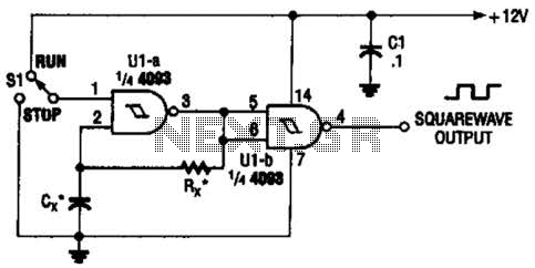
Two gates of the Quad 4093 are utilized to create an oscillator. The resistor (R) can range from approximately 5 kΩ to around 10 kΩ. The capacitor (Cx) can vary from about 10 pF to higher values, with the...

The use of a differential capacitor enables temperature compensation in an LC circuit utilizing an NFO and N1500 ceramic. C6 serves as a differential capacitor featuring two stators and one common rotor. When one stator's capacitance reaches its maximum...
This is a complete alarm system with five independent zones suitable for a small office or home environment. It utilizes three CM integrated circuits and features a timed entry/exit zone, four immediate zones, and a panic button. There are...
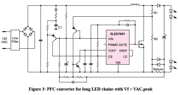
The incandescent light bulb has been the leading choice for lighting applications since its introduction in the late 19th century; however, its efficiency has consistently remained below five percent. Growing global ecological awareness and the demand for more cost-effective...
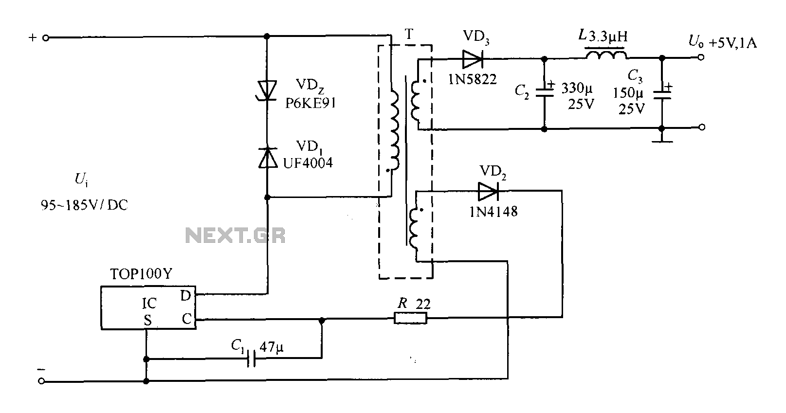
The TOP100Y is a flyback DC switching power supply circuit with a +5V, 1A output. This power supply features a feedback circuit that directly regulates the output voltage, making it suitable for applications that require electrical isolation and minimal...
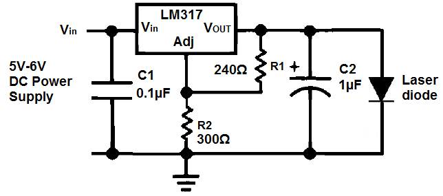
Unlike LED light, a laser's light output is more concentrated, resulting in a smaller and narrower viewing angle. This characteristic necessitates that the laser light be directed more precisely at its source for effective detection. Laser light is also...