
Battery Monitor Circuit
The battery monitor circuit typically consists of a voltage divider, an operational amplifier (op-amp), and a display unit, such as an LED or an LCD. The voltage divider is used to scale down the battery voltage to a level that is safe for the op-amp input. This ensures that the op-amp can accurately process the voltage without being damaged by excessive voltage levels.
The op-amp is configured as a comparator, which compares the scaled voltage from the voltage divider against a reference voltage. This reference voltage can be set using a precision voltage reference or another voltage divider connected to a stable power source. When the battery voltage falls below a certain threshold, the op-amp output changes state, triggering the display unit to indicate that the battery is undercharged.
The display unit can be configured to show the battery voltage level in real-time or provide a simple indicator (such as a green LED for adequate charge and a red LED for low charge). In more advanced designs, a microcontroller can be incorporated to provide additional features such as data logging, alarms, and even communication with other devices.
Power for the circuit can be derived directly from the battery being monitored or through a separate power supply. It is crucial to ensure that all components are rated for the maximum expected battery voltage to prevent damage and ensure reliable operation. Proper PCB layout and component selection are also essential to minimize noise and improve the accuracy of the voltage readings.
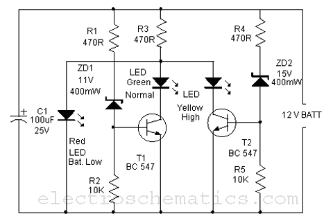
In summary, this battery monitor circuit serves a vital role in maintaining the health of a 12-volt lead-acid battery by providing a simple yet effective means of monitoring its charge level, thereby extending its operational life.Here is a simple Battery Monitor circuit for a quick check of 12 volt Lead-Acid Battery. Battery charge should be constantly monitored to increase the life.. 🔗 External reference
Related Circuits
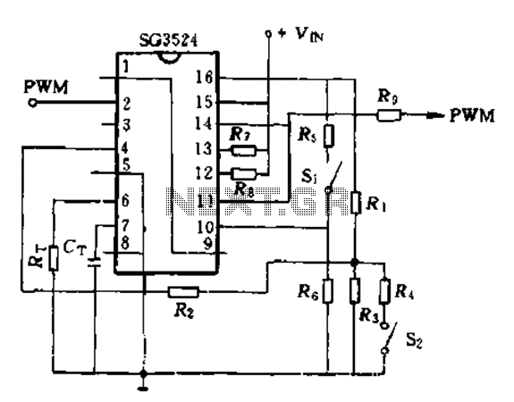
The SG3524 is utilized solely as a pulse width modulator. The error amplifier is configured in a follower arrangement. As illustrated in Figure 10-7, the ACR output connects to PWM output pin 2, which serves as the control signal....
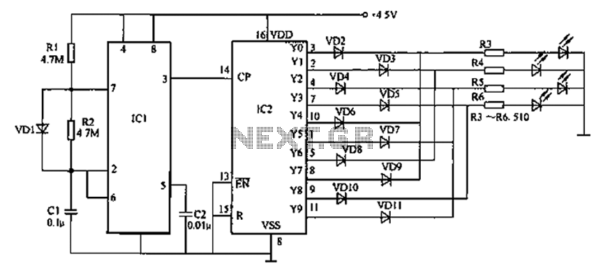
Prolonged reading or writing, maintaining a close distance between the eyes and the book, and insufficient lighting are primary contributors to decreased vision. This example describes a visual fatigue eliminator designed to alleviate eye fatigue and prevent myopia. The...
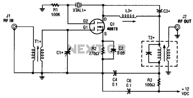
The second gate (G2) of a MOSFET can be utilized to integrate a crystal oscillator within the same stage as a frequency mixer. While this technique is common in tube technology, it is rarely implemented in dual-gate MOSFET circuits....
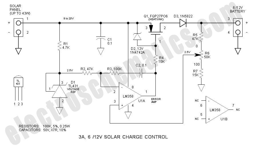
This solar charge controller integrates multiple features into a single design, including a 3A current rating, low dropout voltage (LDO), and a range of voltage adjustment capabilities. The solar charge controller is a critical component in solar energy systems, tasked...
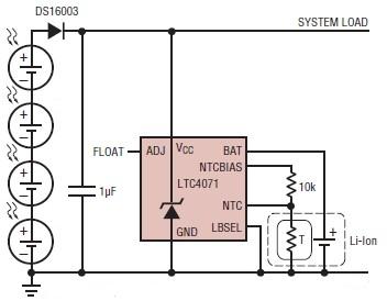
A simple solar-powered battery charger circuit can be designed using the LTC4071 Li-Ion/Polymer Shunt Battery Charger System with Low Battery Disconnect. When VCC reaches the programmed float voltage (4.1V with ADJ floating), the LTC4071 shunts excess current not used...

This circuit is a Phase-Locked Loop (PLL) system designed for use as an FM demodulator. The output of the Voltage-Controlled Oscillator (VCO) follows the FM signal, with the input voltage to the VCO being proportional to its output frequency....