
INA321 322 a low-cost medium accuracy ECG machine ECG amplifier
The ECG amplifier circuit utilizing the INA321 and INA322 operational amplifiers is designed for effective signal amplification from electrocardiogram (ECG) electrodes placed on the patient's skin. The INA321 and INA322 are specifically configured for low-noise, low-drift applications, making them suitable for medical instrumentation. The input stage involves capturing weak electrical signals generated by the heart, which are then amplified by the INA321/322 to a level suitable for further processing.
The operational amplifier OPA336 is employed in a non-inverting configuration to achieve a significant voltage gain of 100, which is crucial for enhancing the ECG signal while maintaining fidelity. The use of a 2MΩ resistor for common-mode voltage rejection is essential in minimizing interference from external electrical noise, thereby improving the accuracy of the ECG readings.
The feedback mechanism implemented by the second OPA336 connected to the REF terminal of the INA321/322 ensures that the bias voltage remains stable, allowing for consistent output even with variations in input signals. This feedback loop is vital for maintaining the integrity of the ECG signal, particularly when the patient’s physiological conditions fluctuate.
The circuit design incorporates a voltage follower configuration using the OPA336 to drive the right leg, which is a common practice in ECG systems to reduce common-mode noise. This configuration helps to improve signal integrity by providing a stable reference point and minimizing ground loops.
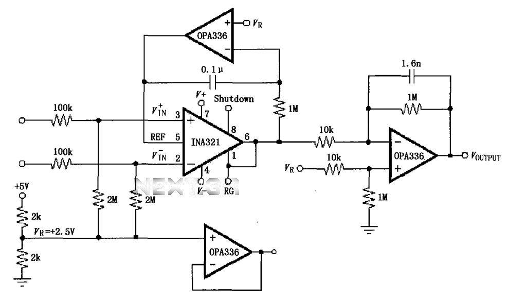
Furthermore, the ability to adjust capacitance values in the filtering stage allows for customization based on specific application requirements. By selecting appropriate capacitors, the circuit can be optimized for different frequency responses, thus tailoring the output to effectively filter out unwanted noise while preserving the essential characteristics of the ECG signal. This flexibility is advantageous in various clinical settings where ECG monitoring is essential. As shown by INA321/322 constitute a low-cost, medium accuracy ECG machine ECG amplifier circuit shown. INA321 input signal from the patients arm around/322, the INA321/322 ampl ified output to the operational amplifier OPA336, OPA336 produce an output voltage from the inverting amplifier VOUTPUT 100 times. Common-mode voltage is done by 2M resistance. VR inverting amplifier OPA336 to provide a bias voltage, the output voltage as a bias voltage for the operating point changes.
Similarly, by another OPA336 form a feedback added to the REF terminal INA321/322 as a bias voltage, INA321/322 6 pin output voltage as a bias voltage is small for a change. The OPA336 as a voltage follower, for the right leg drive. For filter requires different applications, you can change the output of the capacitance value to meet.
Related Circuits

This amplifier was designed to be self-contained in a small loudspeaker box. It can be fed by Walkman, Mini-Disc, iPod, CD players, computers, and similar devices fitted with line or headphone output. Of course, in most cases, you will...
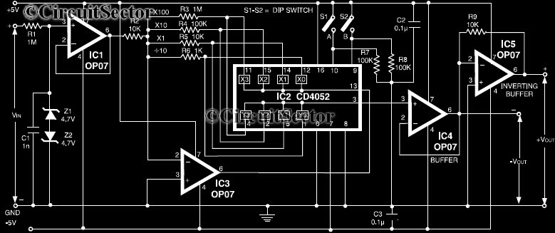
This circuit is a precision amplifier with digital control, designed for signal conditioning of low-output transducers operating in the millivolt range. The resistors R3 to R6 can be user-selected, with values ranging from 1 kilo-ohm to 1 mega-ohm, allowing...
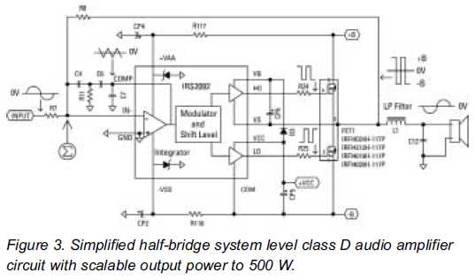
Class D audio amplifiers are now prepared to replace Class AB amplifiers. An integrated high-voltage audio driver simplifies the design and construction of high-power audio systems. Class D audio amplifiers, also known as switching amplifiers, utilize pulse-width modulation (PWM) to...
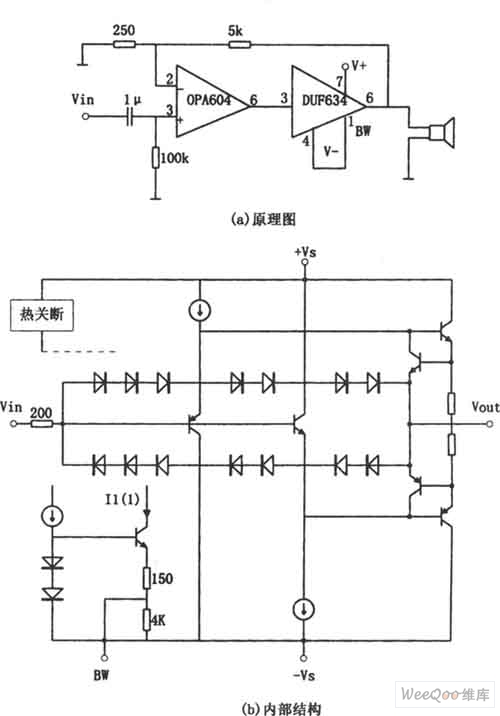
The provided image depicts a high-performance and low-power audio power amplifier circuit. The initial stage utilizes the MOSFET hi-fi operational amplifier OPA604, while the subsequent stage employs the high-speed buffer BUF634. Voltage series negative feedback is implemented between the...
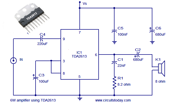
A simple and easy-to-build Hi-Fi audio power amplifier circuit is presented here. This 6-watt Hi-Fi audio amplifier circuit utilizes the TDA2613 integrated circuit (IC). The circuit design employs the TDA2613, which is a high-performance audio amplifier IC known for its efficiency...
This is a status panel driver circuit. This circuit is used to turn on lamps or LEDs in a graphic panel that represent faults, actions, and the status of an application. The status panel driver circuit is designed to control...