
TDA4866 test circuit diagram
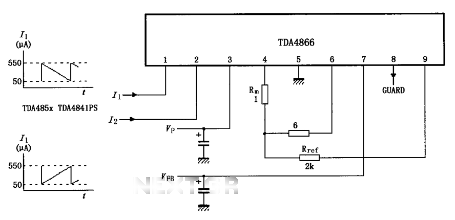
The TDA4866 test circuit is designed to evaluate the performance of the TDA4866 integrated circuit, which is commonly used in vertical deflection applications in television and display systems. The circuit's operation is initiated by the application of a positive supply voltage (VP), which powers the internal components and facilitates the generation of the necessary waveforms for vertical deflection.
The feedback voltage (VFB) is critical for maintaining the stability and accuracy of the output waveform. In this configuration, the circuit is capable of handling a feedback voltage of 40V, with a maximum allowable voltage of 60V, ensuring that the circuit operates within safe limits under various load conditions. The reference resistor (Rref) plays a pivotal role in determining the feedback loop gain, which influences the overall performance of the circuit.
The differential input stage is designed to receive input signals that represent the desired vertical deflection. The inverting input terminal processes these signals, allowing for the generation of a vertical sawtooth waveform. This waveform is essential for driving the vertical deflection coils in a display system, providing the necessary movement of the electron beam or image pixels.
The output stage amplifies the sawtooth voltage, ensuring that it reaches the appropriate levels required for effective deflection. The use of a dummy load resistance simulates the behavior of a deflection coil, allowing for accurate testing and evaluation of the circuit's performance under realistic conditions.
Capacitors and resistors are selected based on the desired frequency response and stability of the circuit. The feedback capacitor (CFB) of 22 microfarads is chosen to filter out high-frequency noise, while the capacitor (CSP) can vary between 10 and 330 nanofarads, allowing for tuning of the circuit's response. The series resistor (RSP), ranging from 10 to 22 ohms, is used to limit current and protect the circuit from potential overload conditions.
Overall, the TDA4866 test circuit is a comprehensive setup for evaluating the functionality and performance of the TDA4866 integrated circuit in vertical deflection applications, providing essential insights into its operation and characteristics. As shown for the TDA4866 test circuit. When the positive supply voltage VP, supply voltage VFB plus flyback circuit operates when the input signal changes from 1 foot and 2 fee t inside the differential input stage input to the inverting input terminal and inverting input terminal, vertical sawtooth voltage output stage to enlarge after the output of 6 feet and 4 feet. The test circuit used as a dummy load resistance 6 alternative deflection coil, while the output signal is fed back through Rref 9 feet.
40V VFB 60V, RFB 100, CFB 22 F, CSP 10 ~ 330nF, RSP 10 ~ 22 .
Related Circuits
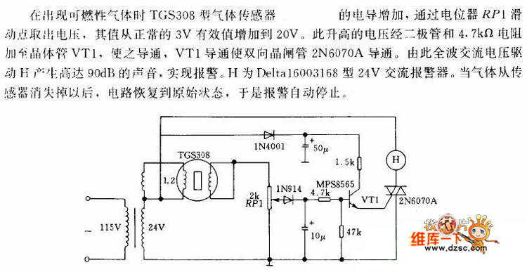
In the presence of combustible gas, the conductance of the TGS308 gas sensor increases, causing the voltage at the potentiometer RP1 slide point to rise from a normal 3V RMS to 20V. This elevated voltage is applied to transistor...
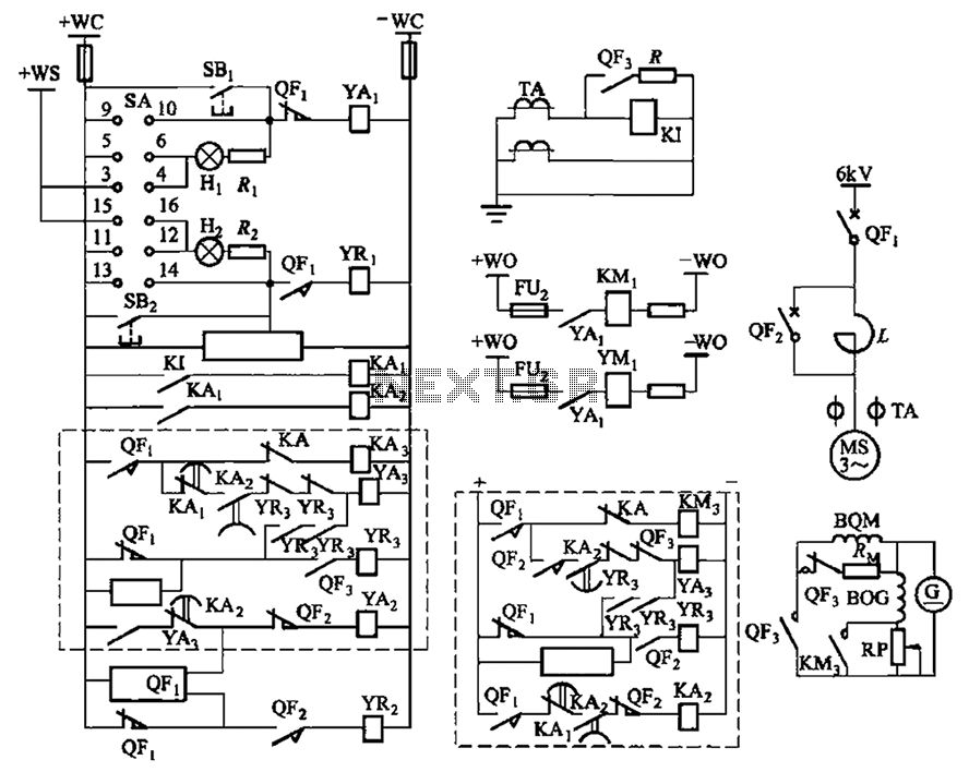
The circuit depicted in Figure 3-189 includes various components such as switch SA, closing button SBi, trip button SBz, de-excitation switch Yaa, and off trip coil YR3. The excitation switch contacts are represented by QF3, which serves as a...
The local oscillator operates at frequencies of 1 GHz or higher, utilizing a common collector circuit, which makes it challenging to generate low-frequency self-oscillation. Typically, the local oscillator signal is passed through a buffer amplifier stage before being applied...
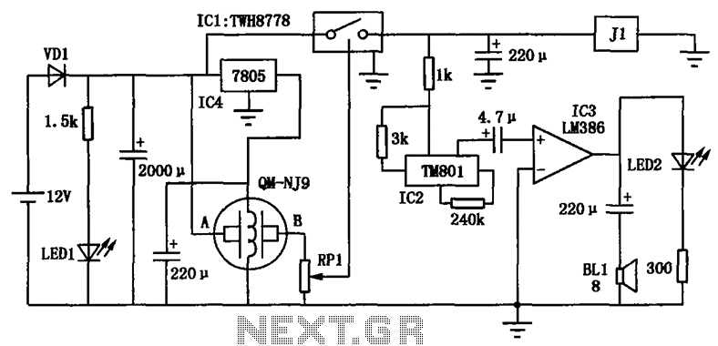
The alcohol detection alarm controller circuit is illustrated in the figure. It utilizes the QM-NJ9 alcohol gas sensor, which detects the presence of alcohol vapors. When alcohol is detected, the resistance between the AB-QM-NJ9 decreases, causing the wiper of...
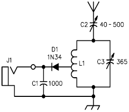
A crystal radio receiver is a very simple radio receiver that requires no battery or external power source, operating solely on the energy harvested from radio waves through a long antenna. A crystal radio receiver is a passive radio receiver...
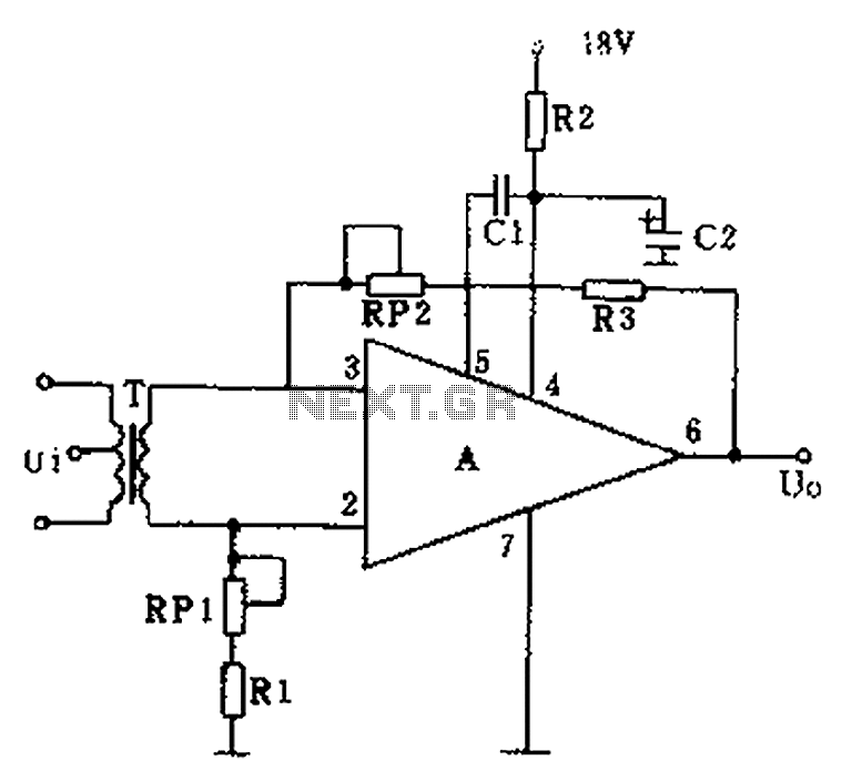
The operational amplifier A is utilized in an audio preamplifier circuit. Its advantages include compact size, low noise, low power consumption, and excellent consistency. The operational amplifier can achieve significant negative feedback while increasing output without distortion. The signal...
Warning: include(partials/cookie-banner.php): Failed to open stream: Permission denied in /var/www/html/nextgr/view-circuit.php on line 713
Warning: include(): Failed opening 'partials/cookie-banner.php' for inclusion (include_path='.:/usr/share/php') in /var/www/html/nextgr/view-circuit.php on line 713