
Basic Crystal Radio ReceiverCircuit by Elmer G. Osterhoudt
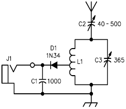
A crystal radio receiver is a passive radio receiver that utilizes the energy from radio waves to produce audible sound without the need for an external power supply. This type of receiver typically consists of an antenna, a tuning circuit, a detector, and a headphone or speaker. The antenna captures radio frequency signals, which are then tuned to a specific frequency using a variable capacitor and an inductor in the tuning circuit.
The detector, often a crystal diode, rectifies the modulated radio signals, converting them into audio signals. The audio output can be heard through high-impedance headphones or a small speaker, which is connected to the output of the detector. The simplicity of the crystal radio receiver lies in its minimal components and the absence of active components, making it an excellent project for beginners in electronics and radio technology.
To enhance performance, factors such as the length of the antenna, the quality of the tuning circuit, and the type of detector used can be optimized. Longer antennas generally improve reception, while a higher quality diode can lead to better signal detection. Overall, the crystal radio receiver serves as an educational tool for understanding the principles of radio communication and the basic operation of radio circuits.A crystal radio receiver is a very simple radio receiver which needs no battery or power source and runs on the power received from radio waves by a long.. 🔗 External reference
Related Circuits
This firmware is intended to run on Atmel ATmega163 (499 bytes for program memory) or AT90S8515 (298 Bytes for program memory). Communications with the terminal is via RS-232 at 9600 baud. Use 8 data bits, 1 stop bit, and...
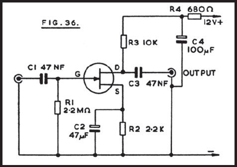
Figure 36 illustrates the circuit of a preamplifier featuring a high impedance input and an output circuit designed for coupling to a main amplifier. This configuration is particularly advantageous for applications such as amplifying the signal from a crystal...
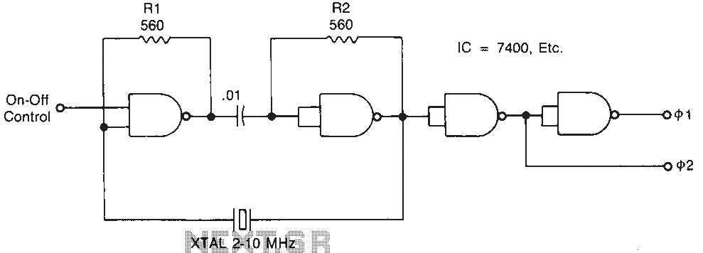
Temperature-stable resistors R1 and R2 are used in NAND gate configurations, ensuring that the switches operate in the linear region. Capacitor C1 functions as a DC component at the operating frequencies. Additionally, the impedance must remain below 0.1 ohm....
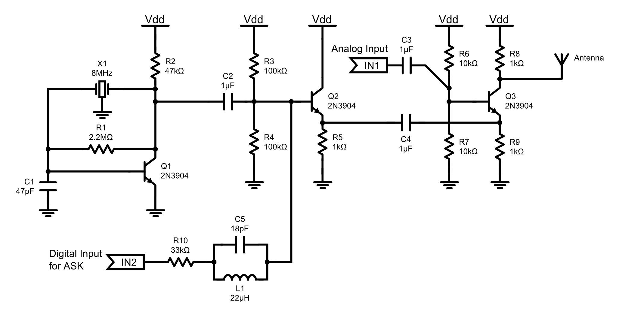
This is an 8MHz amplitude modulated (AM) radio transmitter designed primarily for practical applications and as an educational exercise in electronics. The objective was to create a simple radio transceiver that could be used in future projects requiring basic...
Broadcast band frequency modulation (FM) radio was developed to address issues of noise and fidelity present in amplitude modulation (AM) broadcasts. The initial FM receivers featured complex designs, utilizing a superheterodyne converter, wideband intermediate frequency (IF), limiter stage, and...
The analog interface is a straightforward analog-to-digital converter that accepts the analog video output from the RF/IF board and converts it into a format that can be read by a PC games port. The joystick input of the games...
Warning: include(partials/cookie-banner.php): Failed to open stream: Permission denied in /var/www/html/nextgr/view-circuit.php on line 713
Warning: include(): Failed opening 'partials/cookie-banner.php' for inclusion (include_path='.:/usr/share/php') in /var/www/html/nextgr/view-circuit.php on line 713