
The driver alcohol detection alarm controller circuit diagram
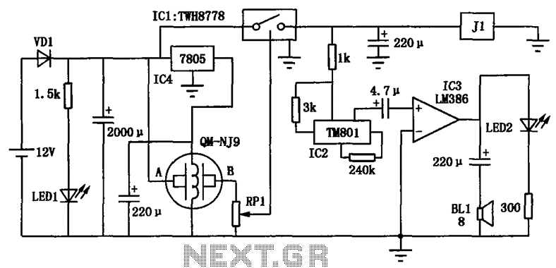
The alcohol detection alarm controller circuit operates as a safety mechanism to prevent driving under the influence. The QM-NJ9 sensor is sensitive to alcohol vapors, providing an essential first line of detection. When alcohol is present, it reduces the resistance in the circuit, which is a critical parameter for the operation of the wiper potentiometer RPl. As the resistance decreases, the voltage at the wiper increases, and once it reaches the predetermined threshold of 1.6V, it activates the TWH8778 power switching device.
The TWH8778 is designed to manage high currents and voltages, allowing it to effectively control the subsequent components in the circuit. The activation of the TM801 integrated circuit generates an audible alarm through the LM386 amplifier, which is a low-voltage audio amplifier capable of delivering sufficient power to drive the BL1 speaker. This audible signal serves as a warning to the driver and surrounding individuals.
In conjunction with the alarm, the relay J1 plays a crucial role in the overall functionality of the system. When energized, it interrupts the vehicle's ignition circuit by opening its break contact. This action prevents the engine from running, thereby stopping the vehicle and mitigating the risk of an accident due to impaired driving. The design of this circuit emphasizes safety and responsiveness, making it an effective tool for enhancing road safety by deterring individuals from driving while intoxicated. The integration of sensor technology with alarm and relay systems exemplifies a practical application of electronics in public safety initiatives. As shown in FIG alcohol detection alarm controller circuit. QM-NJ9 for alcohol gas sensors, if detected the odor of alcohol, the AB-QM-NJ9 between resistance becomes smaller, t he wiper potentiometer potentiometer RPl increases. When the potential rise to l.6V, ICl TWH8778 power switching device is turned on, the IC2 IC TM801 voice work, which outputs the integrated amplifier IC3 LM386 were pushing the power amplifier speaker BLl alarm. At the same time, the relay J1 was electric action, its break contact off, cut off vehicle ignition circuit, forcing the engine stall, the driver to control drunken driving purposes.
Related Circuits
This is a compact, easy-to-build amplifier that utilizes a single integrated circuit (IC) to deliver 40 watts of audio power. It is well-suited for amplifying audio signals from devices such as mobile CD players or iPods. The integrated circuit...
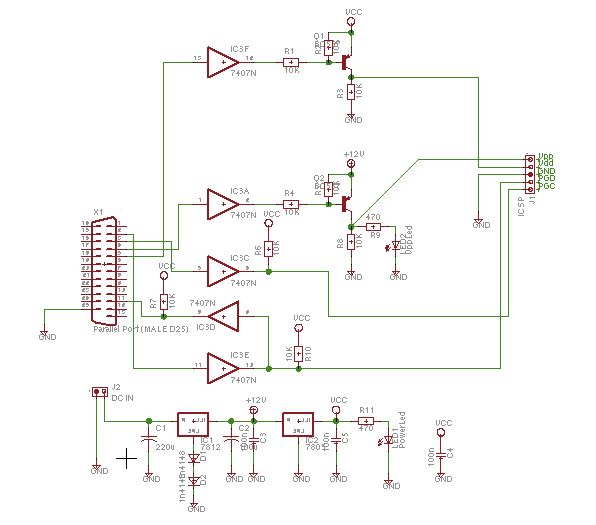
Schaer is a generic programmer circuit capable of uploading and downloading firmware to and from several electronic devices, such as microcontrollers. The Schaer programmer circuit is designed to facilitate the transfer of firmware between a host computer and various electronic...
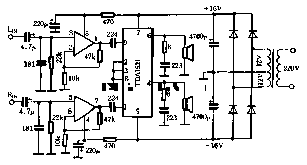
The first power amplifier circuit illustrated in Figure 5-88 utilizes the NE5532 operational amplifier, configured as a line amplifier, and features the TDA1521 power amplifier. This circuit operates with a dual power supply and eliminates the need for coupling...
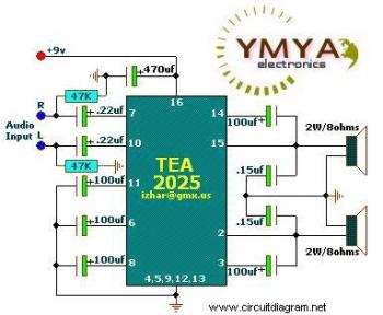
This is a simple portable audio amplifier circuit. The circuit is built around the TEA2025 integrated circuit, which is a monolithic audio amplifier housed in a 16-pin dual in-line package manufactured by UTC. The circuit features an internal thermal...
This is a complete alarm system with 5 independent zones suitable for a small office or home environment. It uses just 3 CMOS ICs and features a timed entry/exit zone, 4 immediate zones, and a panic button. There are...
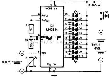
The LM3914A bar graph LED is utilized as a voltmeter for testing batteries. This circuit operates on a 4.5-V battery and compares the battery under test with an internally generated reference, established by resistors R1, R2, and potentiometer P1....
Warning: include(partials/cookie-banner.php): Failed to open stream: Permission denied in /var/www/html/nextgr/view-circuit.php on line 713
Warning: include(): Failed opening 'partials/cookie-banner.php' for inclusion (include_path='.:/usr/share/php') in /var/www/html/nextgr/view-circuit.php on line 713