
Basic circuit diagram connection of signal and power ISOll3
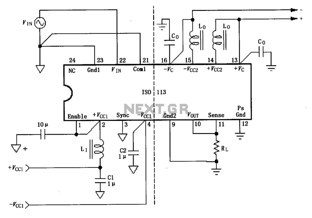
The ISO113 is a precision isolation amplifier designed for applications requiring signal isolation and power supply decoupling. The schematic typically includes multiple power supply terminals, each equipped with bypass filters to ensure stable operation and minimize noise. These filters are crucial, especially when the output current of the isolated power supply exceeds 15mA, as they help maintain signal integrity.
In scenarios where higher current is anticipated, the connection of an external filter to the +Vcc1 pin is recommended to further enhance performance. The output pin of the isolation rectifier (Vcc2) serves to provide isolated power to the amplifier, while the amplifier's input supply pins (Vc) can be linked to additional ripple filters or calibrators, depending on the specific application requirements.
To address potential voltage drop issues caused by long wiring, the Com1 pin is strategically connected to the signal source, and the Sense pin is linked to the upper end of the load. This configuration aids in accurate signal transmission by compensating for any losses incurred due to wire resistance.
Grounding is facilitated through the Gnd1 connection to Com1, ensuring a common reference point for the circuit. The VOUT and Sense pins are interconnected at their respective sockets, and the system includes a safety feature where a low TTL level disables the internal DC-DC converter. This feature is critical for preventing unwanted operation and protecting the circuit during fault conditions.
The internal transformer provides coupling between the DC/DC converter and the isolation amplifier input power, ensuring that the isolated signals are appropriately powered. Furthermore, each power pin in the circuit is equipped with a 0.1µF capacitor to ground, which serves to filter out high-frequency noise and stabilize the power supply, enhancing the overall reliability and performance of the ISO113 circuit configuration. As shown for the basic connection circuit ISO113 signal and power supply. Each power supply terminal must have a bypass filter. When isolated power supply output current is gre ater than 15mA, we recommend the use of such power pin + Vcc1 pin external Ji filter. Isolation rectifier output pin ( Vcc2) and amplifier input supply pins ( Vc) can be attached to the ripple filter or calibrator. Com1 feet to the signal source, Sense then load the upper end, to reduce the transmission due to the long wires cause a voltage drop caused by the error.
Gnd1 connected to Com1, VOUT and Sense in the relative socket connection, or TTL low will disable the internal DC-DC converter works. Internal transformer coupling DC/DC converter by the isolation amplifier input power, all power has feet within a 0.1 F capacitor to ground.
Related Circuits
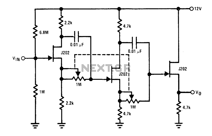
Each J202 JFET stage provides up to 180 degrees of phase shift controlled by a 1 megohm potentiometer. The potentiometer allows for complete control of the groups. JFETs are ideal for the designated circuit because they do not load...
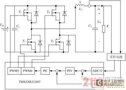
Traditional UPS systems use analog circuit control, which presents significant limitations for both manufacturers and users, regardless of whether they employ technology or SPWM technology. With advancements in information technology, the introduction of high-speed digital signal processing chips, known...

This second-order filter, designed for audio applications, utilizes an LM1458 or a similar operational amplifier. It is tunable with a cutoff frequency ranging from 30 Hz to 300 Hz. The resistors R2a and R2b are ganged log-taper potentiometers. The described...
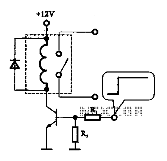
A relay control circuit is illustrated, which is commonly found in microwave switches. This circuit facilitates the operation of various components such as the power supply switch, electric fans, light bulbs, food turntables, and timers. The relay control signal...
The Brushless DC motor with permanent magnetism is an advanced electrical machine characterized by innovative principles and technology. It consists of three main components: the Brushless DC motor body (BLDCM), a trochanter position transducer (RPS), and a control unit...
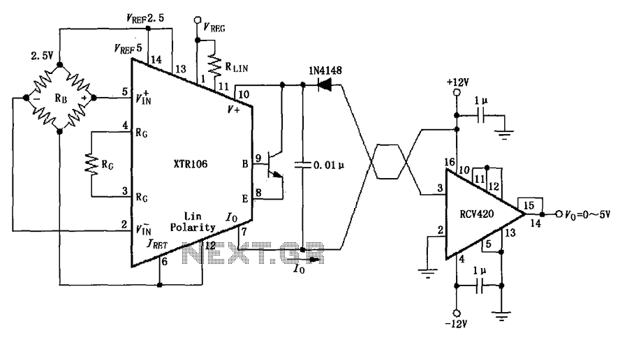
The IN4148 series diode is connected in the V+ line and configured in a loop to prevent damage from reverse voltage conditions. The diode exhibits a forward voltage drop of approximately 0.7V, which affects the supply voltage. The circuit...