
The basic circuit diagram of a differentiator
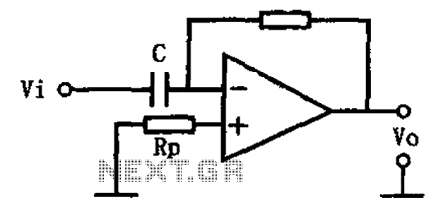
A basic differentiating circuit is designed to produce an output that is proportional to the rate of change of the input signal. In electronic applications, this is particularly useful for processing signals where rapid changes need to be detected, such as in waveform shaping or signal conditioning.
The circuit typically consists of a resistor (R) and a capacitor (C) arranged in a configuration that allows the differentiation of the input voltage (Vin). The output voltage (Vout) is derived across the resistor, and the relationship can be expressed mathematically as Vout = -RC(dVin/dt), where dVin/dt represents the derivative of the input voltage with respect to time. This indicates that the output voltage is inversely proportional to the rate of change of the input voltage.
In practical implementations, the values of R and C must be carefully selected to ensure that the circuit responds appropriately to the frequencies of interest. A high-pass filter characteristic is inherent in this differentiating circuit, allowing high-frequency signals to pass while attenuating low-frequency signals.
The circuit can be further enhanced by incorporating operational amplifiers (op-amps) to improve performance, increase gain, and provide better control over the output characteristics. By using an op-amp in a differentiating configuration, the circuit can achieve greater accuracy and stability, as well as the ability to handle a wider range of input signal amplitudes.
In summary, the basic differentiating circuit serves as a fundamental building block in various electronic applications, enabling the detection and amplification of rapid changes in input signals. As shown for the basic differentiating circuit. The differential operation circuit can input and output, the relationship between the output, between the input:
Related Circuits
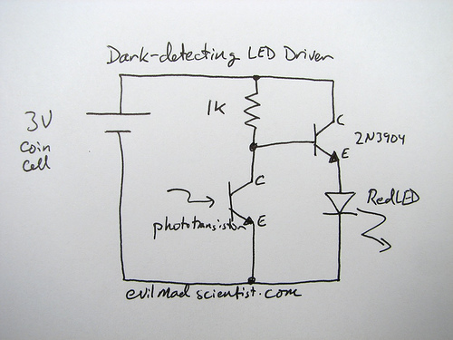
The following circuit illustrates a simple and inexpensive dark-detecting LED circuit. Features include the use of photoresistors, specifically a photocell or LDR, and an LED. This circuit utilizes a light-dependent resistor (LDR) as the primary sensing element. The LDR exhibits...
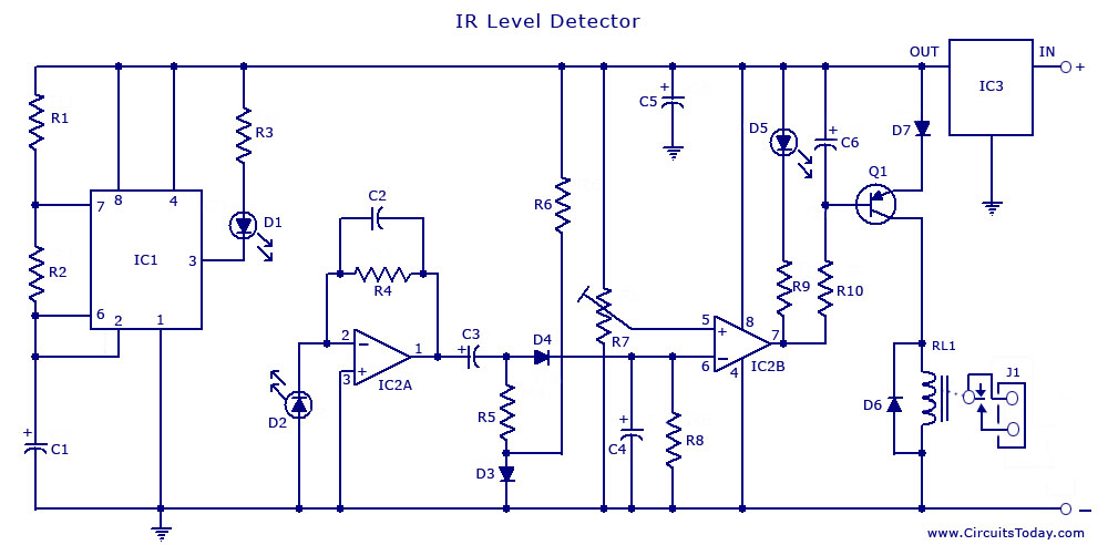
An infrared (IR) sensor or detector circuit diagram utilizing a 555 integrated circuit (IC), primarily employed as a water level or liquid level sensor and proximity detector circuit. The described circuit employs a 555 timer IC configured in a monostable...
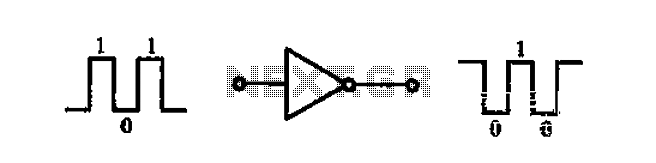
A common-emitter transistor amplifier produces an output signal that is 180 degrees out of phase with the input signal, commonly referred to as an inverting amplifier. When the electrical path for amplifying the pulse signal is activated, this circuit...
This sawtooth generator circuit utilizes a 741 operational amplifier (op-amp) and functions as a musical sound synthesizer. The sawtooth input signal is continuously modified through potentiometer P2 to create varying waveforms. The sawtooth generator circuit primarily employs the 741 op-amp...
The LM324N is part of the LM324 family, which includes four independent, high-gain, internally frequency-compensated operational amplifiers. These amplifiers are designed to operate from a single power supply over a wide range of voltages. Operation from split power supplies...
A sine wave oscillator can be implemented using a Wien-Bridge oscillator, similar to the previous sine wave oscillator circuit; however, another method is now presented. The Wien-Bridge oscillator is a type of electronic oscillator that generates sine waves. It is...
Warning: include(partials/cookie-banner.php): Failed to open stream: Permission denied in /var/www/html/nextgr/view-circuit.php on line 713
Warning: include(): Failed opening 'partials/cookie-banner.php' for inclusion (include_path='.:/usr/share/php') in /var/www/html/nextgr/view-circuit.php on line 713