
Infrared (IR) Sensor/DetectorCircuit using 555 IC
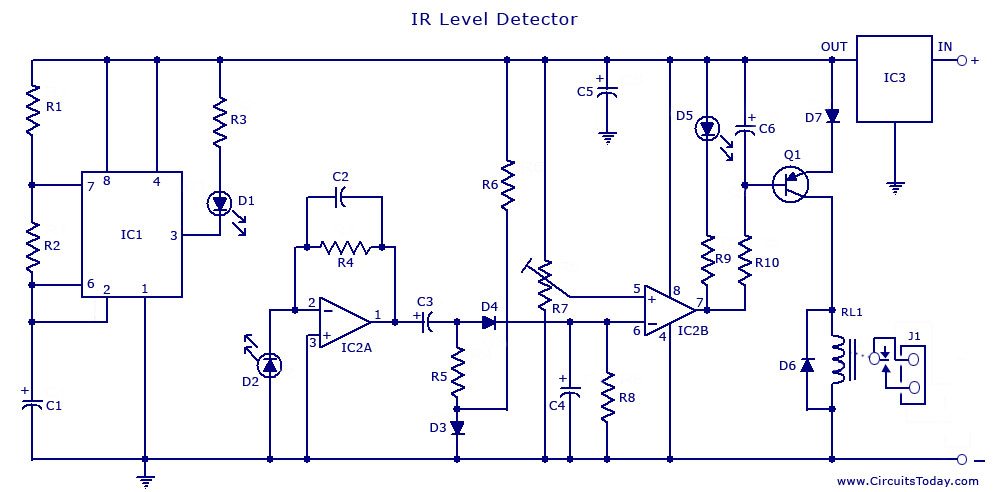
The described circuit employs a 555 timer IC configured in a monostable or astable mode to facilitate the detection of infrared signals. The IR sensor consists of an IR LED and a photodiode or phototransistor. The IR LED emits infrared light, which is reflected back to the photodiode or phototransistor when an object, such as a liquid surface, is present within the detection range.
In the water level sensing application, the circuit is designed to detect the presence of water by measuring the change in the infrared light reflected back to the photodetector. When the water level rises to a certain point, the reflected IR light intensity increases, triggering the 555 timer to output a high signal. This output can then be used to activate an indicator, such as an LED or a relay, to signal that the water level has reached a desired threshold.
For proximity detection, the circuit can be adjusted to sense the presence of nearby objects without physical contact. The distance at which the IR sensor operates can be modified by changing the values of the resistors and capacitors in the circuit. The output of the 555 timer can be configured to drive other components, such as alarms or automated systems, based on the proximity of the detected object.
Overall, this IR sensor circuit using a 555 IC is versatile and can be adapted for various applications, including liquid level monitoring and object detection, making it a valuable component in electronic projects.An Infrared or IR sensor/detector circuit diagram using 555 IC used mainly as Water level or Liquid level sensor and proximity detector circuit.. 🔗 External reference
Related Circuits
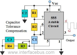
The 555 Timer is configured as an astable multivibrator. Additional components have been incorporated to enhance circuit operation. Upon powering the circuit, the 555 Timer will generate a square wave, determined by the values of Capacitor C1 and Resistors...

This circuit is based on the application note for the L296, a Power Switching Regulator from ST. The primary benefit of utilizing a switching regulator is the minimal heat dissipation observed in this design. In contrast, implementing a series...
A laser trip wire that activates a camera. An ambient light sensor from Vishay, the TEMT6000, operates as an NPN transistor connected to a 555 timer in bistable mode. The output is directed to a logic inverter for quick...
This fluid level sensor circuit is designed to use an AC sensing signal to prevent electrolytic corrosion on the probes. The rectified AC signal is utilized to drive a T1 transistor, which in turn activates a 12-volt relay that...

This chip from Texas Instruments is easy to integrate into designs and is suitable for the assembly of lighting devices. A consistent quality and expected performance can be easily achieved. The complete circuit consists of a control integrated circuit...

This design circuit is for audio graphic equalizers, which are commonly found in commercial products, yet circuits for them are rarely published. The circuit features a simple design that requires an operational amplifier (op-amp) to amplify the input signal....