
fog lamp sensor circuit
The electronic circuit described facilitates the automatic control of fog lamps in towing scenarios, ensuring compliance with safety regulations while enhancing visibility. The core component of this system is the P521 optocoupler, which serves as an isolation device that detects the activation of the trailer or caravan fog lamp. When the fog lamp is energized, it allows current to flow through diodes D1 and D2, which are crucial for protecting the circuit and ensuring proper current routing.
The optocoupler's LED illuminates when current passes through, activating its internal photo-transistor. This action triggers transistor T1, which in turn energizes a relay. The relay serves as a switch that interrupts the power supply to the fog lamp of the towing vehicle, effectively turning it off. This process prevents the potential hazard of glare that could impair visibility for other drivers.
The circuit can be assembled on a perforated circuit board, making it accessible for individuals with basic electronics skills. The compact design allows for easy installation near the rear lamp fitting of the towing vehicle, ensuring that it does not interfere with the vehicle's normal operations. This solution not only adheres to legal requirements but also enhances overall road safety during adverse weather conditions. Proper implementation of this circuit can significantly improve the visibility of the trailer or caravan while minimizing distractions caused by the towing vehicle's fog lamp.For several years now, a rear fog lamp has been mandatory for trailers and caravans in order to improve visibility under foggy conditions. When this fog lamp is switched on, the fog lamp of the pulling vehicle must be switched of to avoid irritating reflections.
For this purpose, a mechanical switch is now built into the 13-way female connector in order to switch of the fog lamp of the pulling vehicle and switch on the fog lamp of the trailer or caravan. For anyone who uses a 7-way connector, this switching can also be implemented electronically with the aid of the circuit illustrated here.
Here a type P521 optocoupler detects whether the fog lamp of the caravan or trailer is connected. If the fog lamp is switched on in the car, a current flows through the caravan fog lamp via diodes D1 and D2. This causes the LED in the optocoupler to light up, with the result that the photo-transistor conducts and energies the relay via transistor T1.
The relay switches of the fog lamp of the car. For anyone who`s not all thumbs, this small circuit can easily be built on a small piece of perforated circuit board and then fitted somewhere close to the rear lamp fitting of the pulling vehicle. 🔗 External reference
Related Circuits
Here is a simple circuit which can be used for decoration purposes or as an indicator. Flashing or dancing speed of LEDs can be adjusted and various dancing patterns of lights can be formed. The circuit consists of two...

The circuit illustrated in Figure 3-132 represents an automatic round-trip plug braking circuit. To prevent or limit malfunctions of switch SQ1 and switch SQ2 that could lead to accidents, two additional protection limit switches, S03 and S04, have been...
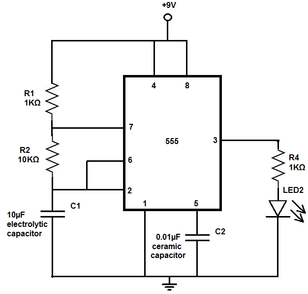
The 555 timer chip is a versatile integrated circuit (IC) that, when connected correctly, can generate pulses of current at specific intervals determined by a resistor-capacitor (RC) network. In this mode, the LED does not remain constantly lit; it...
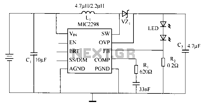
Merry Company (Micrel Inc.) introduced the industry's smallest and most powerful LED driver, the MIC2298, which is widely used in portable electronic devices. The device is a 7W efficient boost DC/DC converter, packaged in a compact 3mm x 3mm...
A DIY GSM jammer schematic diagram designed for use with GSM1900, operating within the frequency range of 1930 MHz to 1990 MHz. The GSM jammer circuit is intended to disrupt communication between mobile phones and base stations within the specified...
IC1D is a CMOS Schmitt trigger oscillator at about 2KHz. It starts and continues to oscillate with a supply down to 1.24V (the lowest output voltage of my LM317 variable power supply) or less. IC1A is an inverter. IC1B...