
R-40-16 ultrasonic receiver circuit
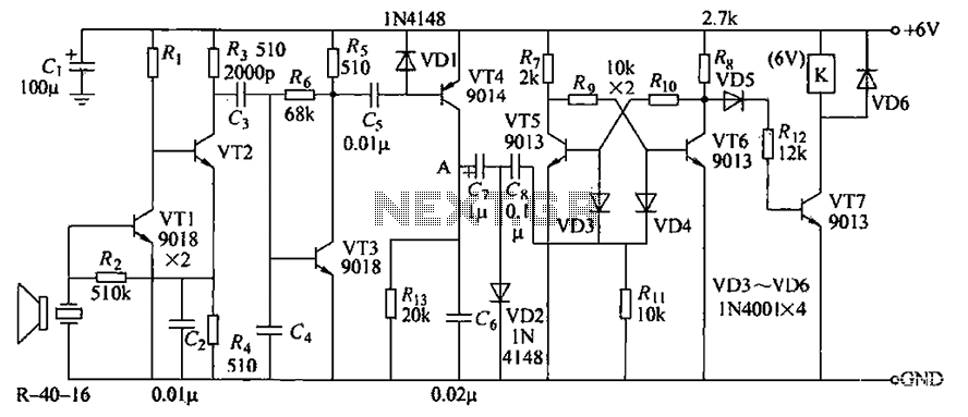
The described circuit operates as a remote control system utilizing a series of transistors for signal amplification and relay control. The multi-stage amplifier, consisting of transistors VT1 to VT3, is designed to boost the weak signal from the transmitter, ensuring reliable operation even at low signal levels. The output from this amplifier is a square wave pulse, which is essential for the bistable circuit operation.
The bistable circuit, controlled by transistors VT4 and VT5, functions as a flip-flop, allowing the circuit to maintain its state until a new trigger pulse is received. The trigger pulse is generated when the transmitter sends a signal, which is coupled through capacitors G and C to transistor VT4. This transistor is responsible for initiating the state change in the bistable circuit. When activated, VT4 allows current to flow, thus turning on VT5 and VT1, which switch the state of the relay K.
The relay K acts as a switch for the connected load, enabling or disabling it based on the state of the bistable circuit. When VT5 is turned off, VT7 is also deactivated, which releases the relay and maintains its state until a new pulse is received. The circuit's design allows for a seamless transition between states, ensuring that the load can be controlled remotely with minimal delay.
The use of transistors in this circuit provides advantages such as low power consumption and high reliability. Additionally, the circuit can be adapted for various applications, including remote control of lighting systems, motors, or other electrical devices, making it a versatile solution for automation needs. Circuit consists VTl. ~ VT7 and other components. Since receiving the signal emitted by the transmitter is very weak emblem, the circuit uses multi -stage amplifier, the output square wave pulse signal to control VT5,1n fly and associated components work status bistable circuit, the transistor VT4 each turned once ( transmitter emits a) trigger signal by G, C fed to the bistable circuit a trigger pulse, VT5, V; 113 a reversal times. When VTfi; when is turned off from, VT5, VT7 closing, relay K release amnesty and maintained. When the next pulse arrives, VT6 by the conduction is turned off. VT7 conduction, the relay pull-K, control the work load. This circuit can be used for remote control of various electrical switches.
Related Circuits

The PM4040F is utilized in switching power supply applications for medium power ranges. It is designed to drive power supplies between 200W and 800W, as illustrated in the accompanying bridge circuit. For power applications below 1000W, an alternative circuit...
This sound-controlled lighting circuit design is utilized to adjust the brightness of connected lights in synchronization with captured sound. The sound-controlled lighting circuit operates by detecting audio signals through a microphone or sound sensor. The circuit typically consists of several...

When the ignition switch is activated, relay K1 receives continuous power, allowing the headlights to be turned on. When the ignition is turned off, timer IC1 is activated, maintaining its power for a duration determined by resistor R1 and...
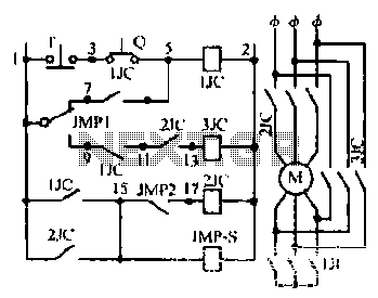
Motor windings are set to connect in a Y configuration while the load is active. The system includes an electric suction mechanism, and the motor is designed to operate under specific conditions. It is rated for 600 revolutions per...
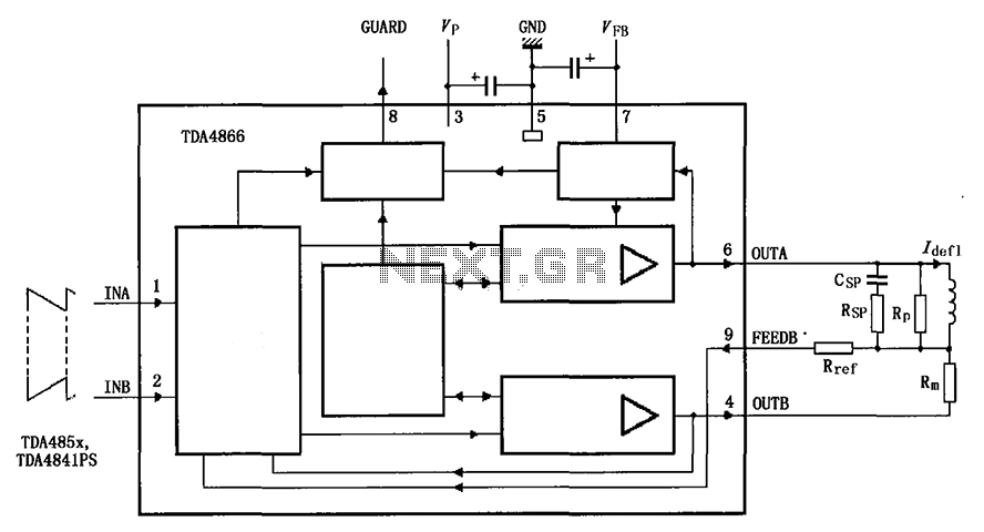
The TDA4866 is a 90-color power amplifier designed for vertical deflection systems, operating at a frequency range of 50 to 160 Hz. The CRMM circuit is implemented to ensure a high current drive input. The amplifier features a dual...

Inverters U1a and U1b are connected in a simple RC oscillator circuit. The frequency is determined by the values of R1, C1, C2, and the internal characteristics of the integrated circuit. As long as the circuit is oscillating, a...