
Sound Controlled Lights Circuit

The sound-controlled lighting circuit operates by detecting audio signals through a microphone or sound sensor. The circuit typically consists of several key components: a microphone for sound detection, an operational amplifier (op-amp) to amplify the audio signals, a rectifier to convert the AC signal into a DC signal, and a microcontroller or a transistor-based control mechanism to modulate the light intensity.
The microphone captures ambient sound waves, converting them into an electrical signal. This signal is then fed into an op-amp, which amplifies the weak audio signal to a suitable level for further processing. The output from the op-amp is usually an alternating current (AC) signal, which is then rectified using a diode bridge or a single diode to produce a direct current (DC) signal that can be used to control the brightness of the lights.
The rectified signal is then processed by a microcontroller or a transistor circuit. If a microcontroller is employed, it can be programmed to analyze the amplitude of the incoming signal and adjust the output to the lights accordingly, creating a dynamic lighting effect that responds to the sound. Alternatively, a transistor-based circuit can be used, where the DC signal controls the base of the transistor, allowing it to regulate the current flowing to the lights, thereby adjusting their brightness.
This circuit can be enhanced by incorporating additional features such as adjustable sensitivity, different lighting modes, or integration with other control systems. Overall, the sound-controlled lighting circuit provides an innovative way to create visually engaging environments that respond to auditory stimuli.This sound controlled lights circuit design is used to control the brightness of the lights attached to it in sync with the sound that is being capturated.. 🔗 External reference
Related Circuits
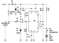
The sections available in this datasheet cover general design considerations for the 555 timer, frequently asked application questions (FAQ), design formulas, and examples of innovative applications. Examples of applications include a Missing Pulse Detector, Pulse Width Modulation (PWM), Tone...
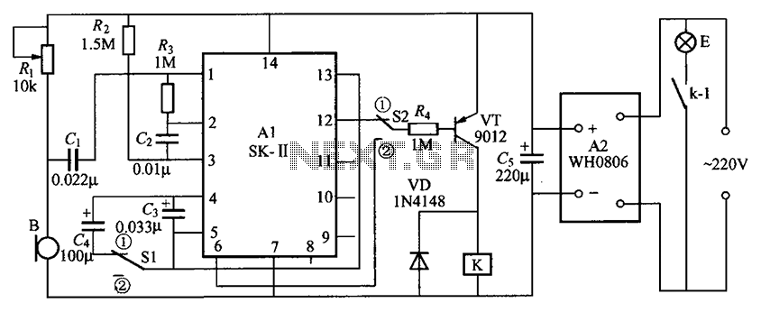
The circuit consists of an acoustic sensor, SK voice circuit, relay control circuit, vocal music circuit, and an AC buck rectifier circuit. The described circuit integrates several key components, each serving a distinct function to achieve the desired operational characteristics....
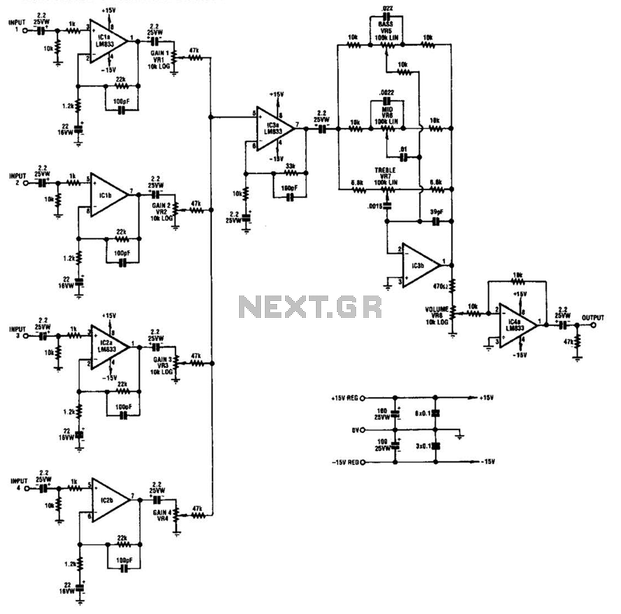
IC1-a, IC1-b, IC2-a, and IC2-b all operate with a gain of approximately 19. Their outputs are combined through level-control potentiometers, and the resulting signal is amplified by IC3-a before being sent to the tone-control stage IC3-b. Finally, the output...
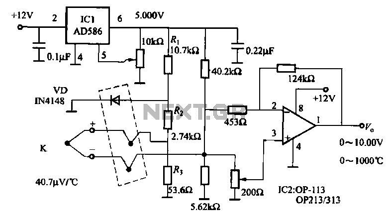
The circuit includes a K-type thermocouple cold junction compensation circuit, a precision 5.000V reference voltage source, and an OP113 operational amplifier. It is capable of measuring temperatures ranging from 0°C to 100°C with a resolution of 0.02°C. The OP113...
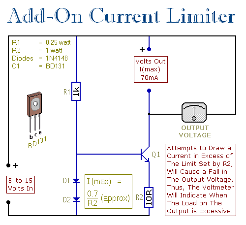
This circuit allows setting a limit on the maximum output current from a power supply unit (PSU). It is particularly useful when powering up a project for the first time or conducting a soak test. By establishing an upper...
The AM transmitter circuit consists of an audio amplifier and an RF oscillator. The oscillator is constructed around transistor Q1 and its associated components. The tank circuit, which includes inductor L1 and variable capacitor VC1, is tunable from approximately...