
A pulse booster circuit
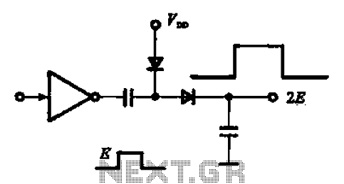
The pulse booster circuit is designed to enhance the amplitude of input pulses, making it suitable for applications where signal strength is critical. The circuit typically employs a combination of transistors, capacitors, and resistors to achieve the desired amplification. In figure (a), the circuit configuration is likely to include a transistor configured as a common emitter amplifier, where the input pulse is fed into the base terminal. The collector terminal outputs a pulse that is amplified, resulting in an output that is double the amplitude of the input pulse.
In figure (b), the circuit is configured to amplify negative pulses. This may involve using a complementary push-pull arrangement of transistors to ensure that both positive and negative portions of the input waveform are effectively amplified. The design may also include feedback mechanisms to stabilize the output and prevent distortion, ensuring that the pulse shape is maintained while increasing amplitude.
The choice of components such as the type of transistors (e.g., NPN or PNP), the values of resistors and capacitors, and the power supply voltage will significantly influence the performance of the pulse booster circuit. Proper selection and configuration of these components are essential for achieving the desired amplification while maintaining signal integrity. Additionally, considerations regarding bandwidth, rise and fall times, and thermal management should be taken into account when designing and implementing a pulse booster circuit for specific applications.A pulse booster circuit When you need to increase the pulse amplitude, pulse boost circuit can be used, its structure, the figure (a) of the circuit can output pulse amplitude is twice the amplitude of the input, figure (b) of the circuit can be obtain twice the amplitude of the negative pulse.
Related Circuits
This circuit is a constant current protection type that limits the output current to a specific value in cases of over-current and short-circuit conditions. When the output current exceeds this limit, the output voltage decreases. The CW200 power management...
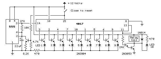
This circuit provides a visual 9-second delay using 10 LEDs before closing a 12-volt relay. When the switch is closed, the 4017 decade counter will reset to zero, illuminating the LED connected to pin 3. The output at pin...
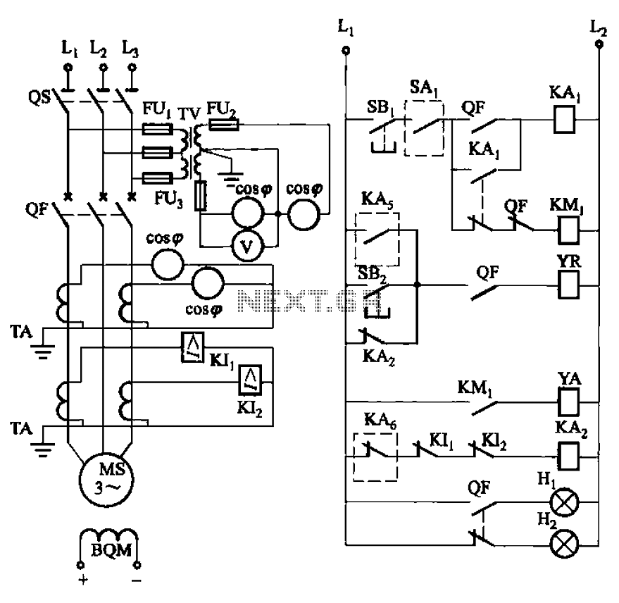
The circuit depicted in Figure 3-186 includes an isolation switch, QF vacuum circuit breakers, YR line for the circuit breaker coil, and YA for the circuit breaker closing coil. Additionally, there is a dashed box representing the excitation device...
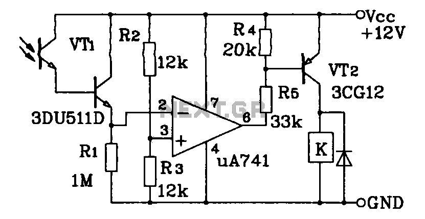
This circuit application utilizes a Darlington phototransistor for light-triggered switching. The design incorporates a Darlington phototransistor and an operational amplifier (op-amp), allowing the circuit to respond to very faint light levels. The circuit can be modified to trigger in...

This modem/fax protector can be utilized in telephone-line connections between a PC or a terminal and a remote computer. In this circuit, the surge voltage protectors (SVPs) are rated at 230 V. Additionally, a proper grounding is essential for...
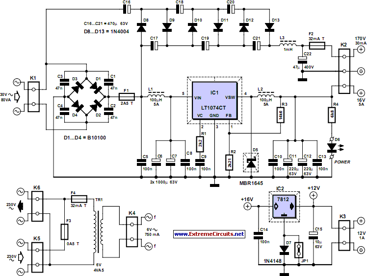
This power supply was designed for use with the Simple hybrid amplifier published elsewhere in this issue. It is suitable for various applications as well. A cascade generator is utilized for the 170 V output, a switch-mode supply provides...