
Three phase torque motor speed control circuit
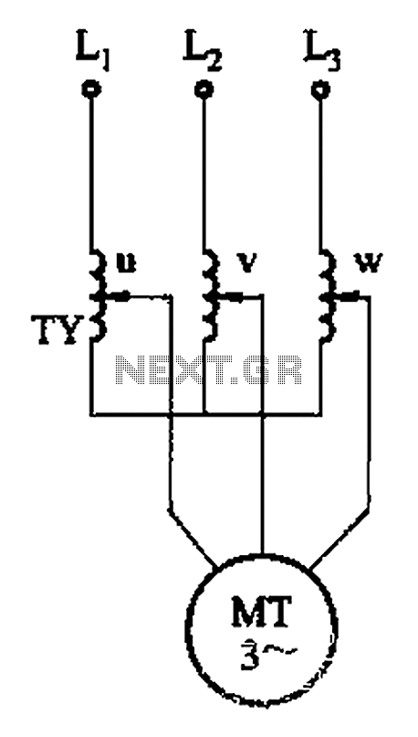
The circuit design in Figure 3-176 focuses on achieving stable motor operation through effective voltage regulation. The use of a three-phase voltage regulator is critical for maintaining consistent voltage levels across the motor phases, which ensures that the motor runs smoothly and efficiently. This regulator compensates for fluctuations in input voltage and load conditions, allowing the motor to reach and maintain its equilibrium state.
The adjustment range of the circuit is a significant advantage, as it enables flexibility in operation. This feature is particularly beneficial in applications where varying load conditions are expected, as it allows for optimal performance across a broader spectrum of operational scenarios. However, the requirement for a three-phase voltage regulator implies an increase in complexity and cost. This component must be carefully selected and integrated into the circuit to ensure it can handle the power levels and operational demands of the motor.
In summary, the circuit in Figure 3-176 provides an effective solution for motor control with a wide adjustment range, though it does come with the trade-off of higher costs associated with the necessary three-phase voltage regulation. Proper design considerations must be taken into account to optimize performance while managing the associated costs. Circuit shown in Figure 3-176. This adjustment method, the motor can run at equilibrium, adjustment range and relatively wide. But requires a three-phase voltage regulator, hig her input costs.
Related Circuits
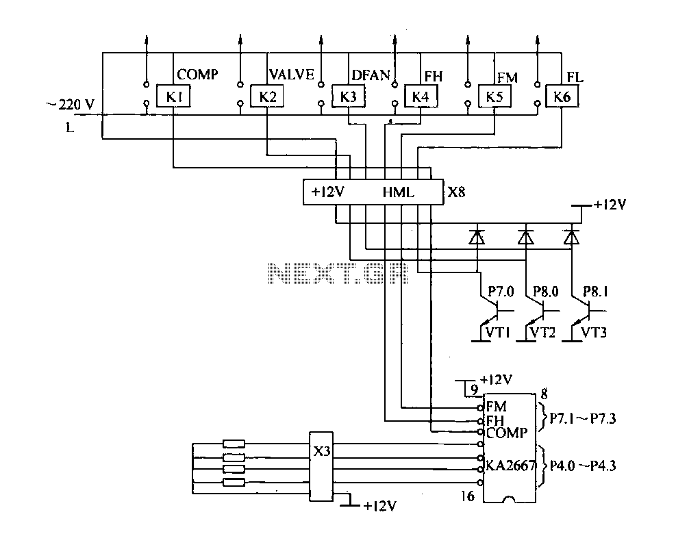
The driving circuit depicted in Figure 18-12 consists of a connection between the driving portion, the microcontroller, and the air conditioning operation components of the bridge. The microcontroller's digital signal levels from ports P4.0 to P4.3 (approximately 12 feet)...
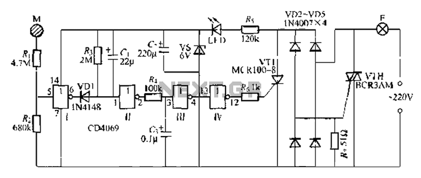
The CD4069 is a digital integrated circuit that utilizes boron to delay the activation of a light touch. It employs a j-wire connection force method and can directly replace a standard light switch without requiring changes to the existing...
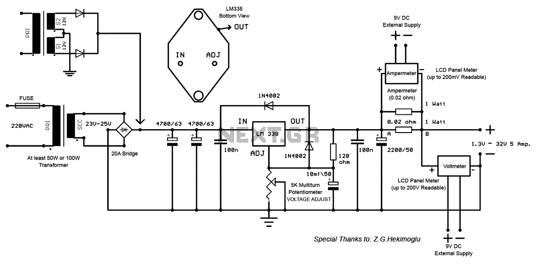
This is an LM338-based power supply that is uncomplicated and easy to construct. It has been in use for an extended period without any issues. The circuit lacks a current adjustment feature, which has been addressed by incorporating an...
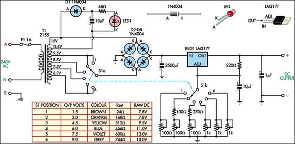
The following circuit illustrates a Battery Replacement Power Supply Circuit Diagram. This circuit is based on the LM317 integrated circuit. Features include the ability to replace... The Battery Replacement Power Supply Circuit utilizes the LM317 voltage regulator to provide a...
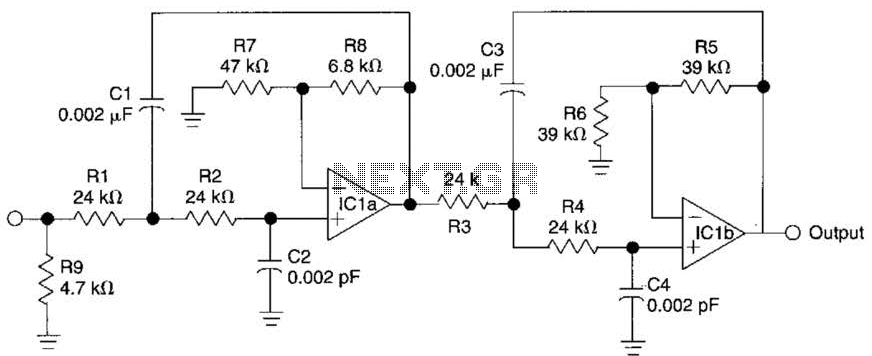
This circuit is a fourth-order low-pass filter designed for operation at kilohertz frequencies. The component values for resistors R1, R2, and capacitors C1, C2, as well as resistors R3, R4 and capacitors C3, C4 can be adjusted for functionality...
Using a transistor will not yield accurate results, and the adjustment process can become quite tedious. The circuit is technically correct; if the tripping point can be adjusted properly, it may function as intended. Vinod states that he created...
Warning: include(partials/cookie-banner.php): Failed to open stream: Permission denied in /var/www/html/nextgr/view-circuit.php on line 713
Warning: include(): Failed opening 'partials/cookie-banner.php' for inclusion (include_path='.:/usr/share/php') in /var/www/html/nextgr/view-circuit.php on line 713