
Battery Replacement Power SupplyCircuit Based On The LM317 IC

The Battery Replacement Power Supply Circuit utilizes the LM317 voltage regulator to provide a stable output voltage suitable for powering devices that typically operate on battery power. The LM317 is a versatile adjustable linear voltage regulator, allowing for output voltages ranging from 1.25V to 37V, depending on the configuration of external resistors.
In this circuit, the LM317 is connected in a standard configuration, with two resistors forming a voltage divider to set the desired output voltage. The input voltage must be higher than the output voltage by at least 3V to ensure proper regulation. Capacitors are placed at the input and output terminals to filter out noise and stabilize the voltage, ensuring smooth operation.
The circuit may also include a heat sink attached to the LM317 to dissipate heat generated during operation, especially when there is a significant voltage drop across the regulator. Additionally, a protection diode can be added in parallel to safeguard against reverse polarity connections.
This power supply circuit is particularly useful in applications where battery replacement is inconvenient or impractical, offering a reliable alternative for powering electronic devices. By adjusting the resistor values, the output voltage can be tailored to match the specific requirements of the connected load, making it a flexible solution for various electronic projects.The following circuit shows about Battery Replacement Power Supply Circuit Diagram. This circuit Based On The LM317 IC. . Features: to replace .. 🔗 External reference
Related Circuits
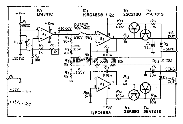
The maximum input voltage is 10V. An operational amplifier (op-amp) is used to provide a reference voltage of 10V, with its stability primarily determined by the characteristics of a temperature-compensated Zener diode (IS2192). The Zener voltage (Vz) can be...
Desulfation is the process of reversing sulfation that occurs in a lead-acid battery over time. Desulfation partially restores the battery's ability to hold a charge, which is diminished due to sulfation. Desulfation is a critical maintenance procedure for lead-acid batteries,...
The TDA7294 amplifier module is a monolithic integrated circuit designed for use as an audio class AB amplifier in hi-fi applications. It has a wide voltage range and output current capability, enabling it to supply the highest power into...
This simple circuit is started running by connecting a twelve volt battery across the terminals, causing the large diameter Light-Emitting Diode to light up. When the battery is removed, the LED stays lit up because the circuit has become...

I constructed this voltage regulator to power my two way mobile radio from the car cigarette lighter circuit. It has many other uses and the voltage can easily be adjusted by the use of a potentiometer. The voltage regulator...
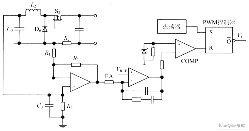
The circuit is capable of enhancing the system power factor to a value exceeding 0.99. It effectively reduces the waveform distortion of the input supply current, ensuring compliance with GB15144 standards, with a distortion index lower than level L....