
For frequent motor starting Y- starting circuit
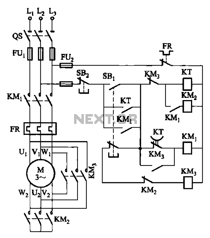
The circuit functions as a motor control system that incorporates safety measures to enhance reliability during power fluctuations. The Y-transfer process indicates that the circuit is designed to manage the operational state of the motor effectively. When contact KMi is deactivated, it triggers a sequence that safely transitions the motor to a stop, thereby preventing damage from abrupt power loss.
The interlocking mechanism between KM2 and KM3 is a critical feature of this design. By ensuring that only one contact can be activated at a time, the circuit minimizes the risk of simultaneous engagement, which can lead to electrical faults or mechanical failures. This arrangement is particularly crucial in applications where motor control is sensitive to rapid cycling or where short circuits may occur.
The schematic would typically include various components such as relays, contactors, and possibly fuses to protect against overcurrent conditions. The design should also consider the ratings of the components to ensure they can handle the expected load and fault conditions. Implementing such a circuit requires careful attention to the specifications of each part, including coil voltages, contact ratings, and the overall configuration to ensure safe and efficient operation.
In summary, the circuit's design prioritizes safety and reliability, making it suitable for applications where power stability is a concern. The careful coordination between the contacts ensures that the motor operates within safe parameters, reducing the likelihood of damage from electrical faults. Circuit shown in Figure 3-41. This circuit Y- transfer process, contact KMi turned off again experienced a process of turning that motor is transitioned in case of power failur e; in addition, KM3 main contact is disconnected when KMz it can be turned on, the two can not simultaneously in the ON state, thereby avoiding frequent start due to a short circuit fault occurs.
Related Circuits
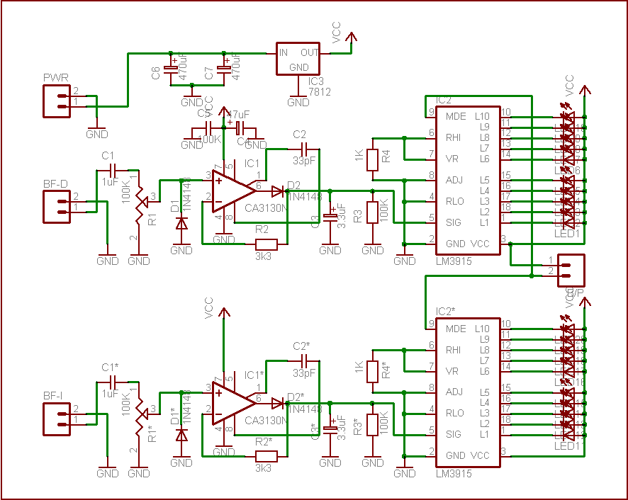
This simple circuit is based on the well-known integrated circuit LM3915. The main characteristic of this integrated circuit is its ability to manage 10 Light Emitting Diodes (LEDs) in a logarithmic scale, with a 3dB difference between the LEDs,...
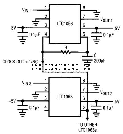
The LTC1063 is a monolithic low-pass filter that provides exceptional DC and AC performance. It features both internal and external clock tunability, with cutoff frequencies reaching up to 50 kHz, a typical output DC offset of 1 mV, and...
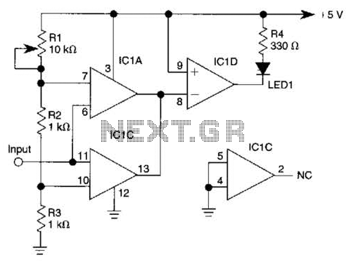
IC1-c functions as a non-inverting comparator, while IC1-a operates as an inverting comparator. Potentiometer R1 and fixed resistors R2 and R3 create a voltage divider chain that provides slightly different voltages to the two comparators. These voltages establish the...
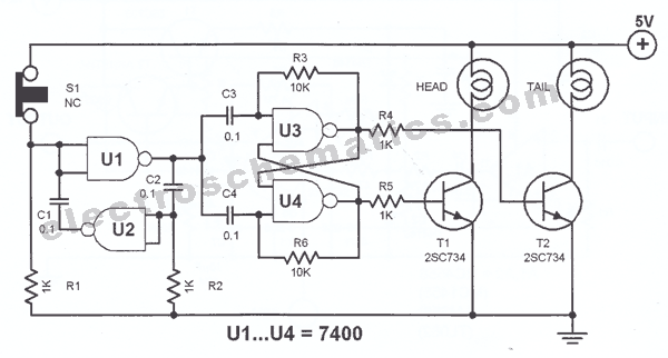
The principle utilized in this electronic head or tail circuit is straightforward: a multivibrator controls a flip-flop. The multivibrator oscillates as long as the button S1 is pressed, while the flip-flop toggles on and off at a frequency of...
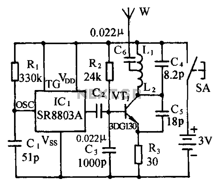
The circuit consists of a language and sound FM transmitter. It is mounted on a 25mm x 35mm PCB, designed to be placed on a table. When activated by pressing the micro switch SA, the circuit transmits an FM...
In a lithium-ion cell, a voltage of 3.8V per cell indicates a state of charge of approximately 50%. It is important to note that using voltage as a fuel gauge is not precise, as cells manufactured by different companies...