
Electronic Head or Tail Circuit
The described electronic head or tail circuit employs a multivibrator and a flip-flop, which are fundamental components in digital electronics. The multivibrator serves as an oscillator that generates a square wave output when the button S1 is pressed. This oscillation continues as long as the button remains engaged, producing a frequency in the kilohertz range. The output from the multivibrator is fed into the flip-flop, which is configured to toggle between its two stable states based on the input signal.
When the button is released, the multivibrator ceases oscillation, and a +5 volts signal is applied to one of the flip-flop's inputs. This input signal is critical as it determines the state of the flip-flop at the moment of button release. The randomness of the output (head or tail) is influenced by two factors: the inherent switching speed of the flip-flop and the reaction time of the user. This design introduces an element of chance, making the circuit suitable for applications requiring randomization.
The use of a single 7400 IC simplifies the design, as this quad two-input NAND gate IC can be configured to create both the multivibrator and the flip-flop functionalities. Careful attention should be given to the decoupling of the circuit to ensure reliable operation. This involves using capacitors to filter out noise and prevent voltage spikes that may occur when the display bulbs are turned off. Proper decoupling is essential to maintain the integrity of the circuit and prevent unintended behavior due to transient voltages.
In summary, this electronic head or tail circuit is a practical example of using basic digital components to create a randomizing mechanism, demonstrating key principles of multivibrator and flip-flop operation while emphasizing the importance of circuit design considerations such as decoupling.The principle used in this electronic head or tail circuit is simple: a multivibrator controls a flip flop. The multivibrator oscillates as long as the buton S1 is pressed and the flip flop switches on and off with a frequency of several kilohertz.
When the button is released, a +5 volts is set at one of the two gates that makes up th multivibrato r. The flip flop latches on at one of the two possible states: head or tail . The state of the flip flop is dependent on the exact time when the button S1 was released. because the speed of the flip flop`s switch overs and the relative inertia of the human reaction, the state at which the flip flop latch is random. The entire circuit is made up of a single 7400 IC. It is important to decouple the circuit and the display bulbs very well to avoid reverse voltages and currents that appear during the switching off of the display bulbs.
🔗 External reference
Related Circuits
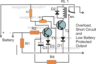
The battery voltage must pass through resistor R1 before reaching the output load. As a result, the current flowing through R1 is proportionately transformed into a voltage across it. When the battery voltage drops below a certain threshold, the...
This receiver is designed around the widely used ZN414 integrated circuit (IC) and operates within the AM band, covering frequencies from 550 to 1600 KHz. To utilize the receiver for Longwave frequencies, it is necessary to replace the coil...
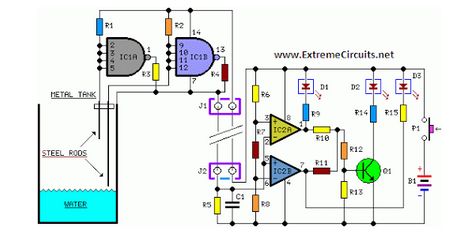
Simple two-wire remote monitoring unit with a three-LED level display, powered by a 9V battery. The entire project was developed at the request of a friend. The remote monitoring unit is designed to provide a straightforward solution for level indication...

The system consists of a MAX1463 precision pressure detection circuit block diagram. The output voltage from the bridge pressure sensor is connected to the MAX1463 inputs IN1+ and IN1-. Controlled by a CPU, the pressure signal undergoes nonlinear calibration...

This smoke detector circuit diagram is based on the SD2 CMOS Photo-Electric Smoke Detector Integrated Circuit manufactured by Supertex Inc. It includes almost all the necessary components to build a simple and highly efficient smoke detector project. The LED...
This class-D audio amplifier is suitable for TV and home stereo systems. The TDA7882 integrated circuit (IC) provides a class-D audio amplifier solution. Since this IC has a single channel output, two units are required for stereo applications. The...
Warning: include(partials/cookie-banner.php): Failed to open stream: Permission denied in /var/www/html/nextgr/view-circuit.php on line 713
Warning: include(): Failed opening 'partials/cookie-banner.php' for inclusion (include_path='.:/usr/share/php') in /var/www/html/nextgr/view-circuit.php on line 713