
Auto-voltage starting time relay control circuit
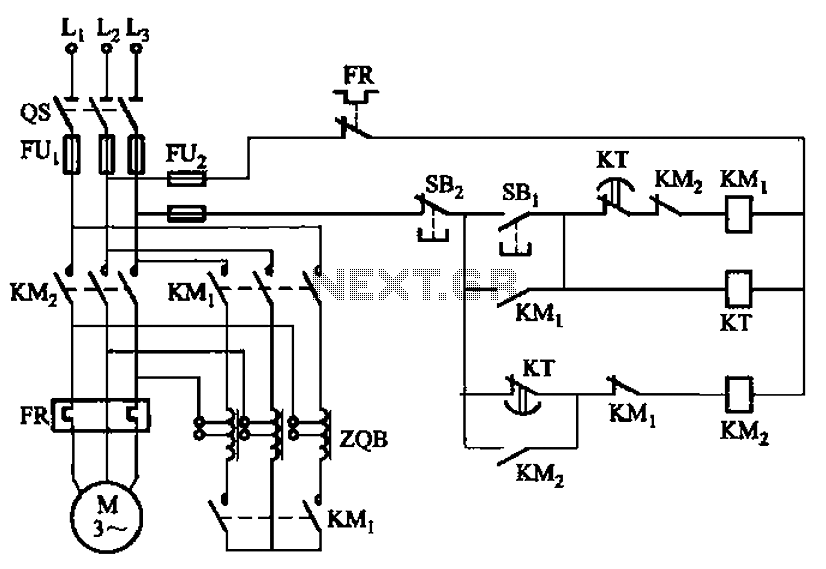
The circuit utilizes an autotransformer, which is a type of transformer that has a single winding that acts as both the primary and secondary winding. This configuration is beneficial for voltage regulation and provides a means to adjust the voltage supplied to the motor during startup. The time relay (KT) is a critical component in this circuit, as it determines the duration for which the autotransformer remains operational.
When the motor is powered on, the KT relay initiates a delay that allows the motor to gradually reach its operational speed. This delay is crucial because it helps to prevent inrush current, which can be detrimental to both the motor and the electrical supply system. The relay is calibrated to match the specific startup time required by the motor, ensuring optimal performance and protection.
As the motor accelerates, the relay monitors the elapsed time and will eventually deactivate the autotransformer once the set delay has expired. This transition is essential for switching the motor to full operational voltage, allowing it to run efficiently without the limitations imposed by the autotransformer.
In summary, the circuit in Figure 3-49 effectively integrates an autotransformer with a time relay (KT) to control the startup process of a motor, providing a reliable method for managing voltage and protecting against excessive current draw during the initial startup phase. Circuit shown in Figure 3-49. The circuit autotransformer out of operation by the time relay KT control. KT delay time is equal to the motor start-up time. Circuit shown in Fig ure 3-49. The circuit autotransformer out of operation by the time relay KT control. KT delay time is equal to the motor start-up time.
Related Circuits
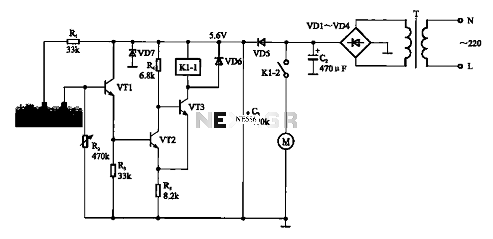
Automatic sprinkler control circuit. This circuit primarily consists of a humidity sensor, a detection signal amplifying circuit (including transistors VT1, VT2, and VT3), a power supply circuit (comprising a filter capacitor C2, a bridge conditioning circuit UR, and a...
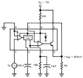
The LM2917 IC chip is specifically designed as a Frequency to Voltage Converter. It requires only a few external components for its operation. The datasheet for the LM2917 IC includes several application examples of the Frequency to Voltage Converter....
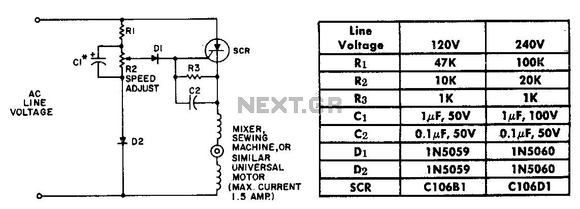
The resistor-capacitor network R1-R2-C1 generates a ramp-type reference voltage that is superimposed on an adjustable DC voltage controlled by the speed-setting potentiometer R2. This reference voltage, available at the wiper of R2, is compared against the residual counter electromotive...
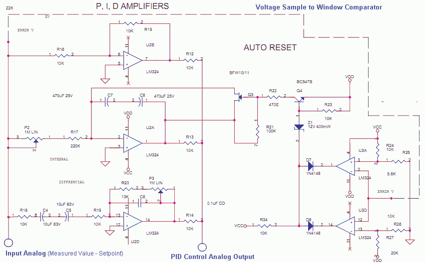
The Measured Value and the Setpoint are two inputs to a control system. The Measured Value is the amplified input from a transducer or sensor for a specific parameter that requires regulation, such as pressure or temperature. The Setpoint...
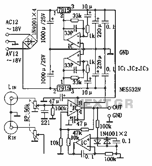
Hi-fi headphones possess a wide frequency response and low distortion, making them incomparable to desktop Hi-Fi audio systems, particularly when compared to some branded headphones and even high-quality speakers. High-fidelity headphones are designed for music listening, offering high resolving...
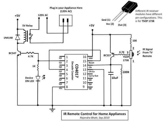
The infra-red (IR) toggle switch project described here is aimed to provide control mechanism for electrical appliances that do not have remote operation features. The goal is to construct a black box where you can plug-in your 120V AC...
Warning: include(partials/cookie-banner.php): Failed to open stream: Permission denied in /var/www/html/nextgr/view-circuit.php on line 713
Warning: include(): Failed opening 'partials/cookie-banner.php' for inclusion (include_path='.:/usr/share/php') in /var/www/html/nextgr/view-circuit.php on line 713