
Infrared mains remote control Switch
So lets see what happens when a key on the remote is pressed. During standby, the output of IR receiver module is High, so BC557 is cut off. The capacitor is fully discharged, and the collector of BC557 is at ground. When a key is pressed on the remote, the train of pulses arrived at the base of BC557 turns it ON and OFF very fast. When it is ON, the capacitor gets charged through the collector current of BC557, and when it is OFF, the capacitor starts to discharge through 100K resistor. But the train of pulses is so fast (38000 pulses per second) that the capacitor doesn't get chance to discharge. So, the bottom line is, every time a key is pressed from the IR remote, a positive going clock pulse is generated at the collector of BC557 transistor. Next comes CD4017, a decade counter. It counts low-to-high going pulses up to 10 that are arrived at its CLK pin (14) and pulls the corresponding output (Q0-Q9) High. When it is just turned on, Q0 goes High, and when it gets a first low-to-high pulse (when a key is pressed from the IR remote) at CLK i/p, Q0 goes Low and Q1 goes High. Q1 output is connected to a LED through a current limiting resistor to indicate the ON/OFF status. The Q1 output is also used to drive a relay switch through a NPN transistor (BC547). I used 5V DC relay that requires about 70mA current from 5V source to turn ON. This current is provided by BC547. Now, lets see what happens when a key is pressed again. The counter advances by 1, Q1 goes Low (relay is OFF), and Q2 goes High. If we connect Q2 to Reset input of CD4017, the counter is going back to the initial condition (Q0 High, Q1 and all others Low), and is ready to get another key press signal to turn the relay ON. This way the switch is toggled every time a key is pressed from the remote.
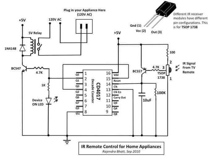
The circuit operates as follows: the TSOP 1738 IR receiver module captures the IR signals from a remote control, which are modulated at a frequency of 38 kHz. When the remote control button is pressed, the output of the TSOP 1738 transitions from a logic high to a logic low, causing the BC557 PNP transistor to toggle. The output from the collector of the BC557 is connected to a 10 µF capacitor and a 100 kΩ resistor, which form a low-pass filter. This configuration converts the rapid pulse train into a single pulse suitable for triggering the CD4017 decade counter.
The CD4017 counts the clock pulses generated by the capacitor discharge and advances its output state with each pulse. The first output (Q0) is initially high, and upon receiving the first pulse, it transitions low while Q1 transitions high, activating the connected LED and driving the relay via the BC547 NPN transistor. The relay, when energized, allows the connected AC appliance to turn on. Each subsequent pulse from the remote control causes the counter to increment, toggling the relay state accordingly.
To ensure that the system resets after reaching the maximum count of 10, the Q2 output can be connected to the reset pin of the CD4017. This configuration allows the toggle switch to be reused, maintaining a user-friendly interface with the IR remote control. The entire circuit is designed to be compact and efficient, providing a practical solution for controlling appliances without built-in remote capabilities.The infra-red (IR) toggle switch project described here is aimed to provide control mechanism for electrical appliances that do not have remote operation features. The goal is to construct a black box where you can plug-in your 120V AC appliance and control ON and OFF operations with any modern IR remote control devices.
Modern IR remote controls generate modulated pulse train of 38KHz frequency when any key on the remote is pressed. With the use of capacitive filtering we will convert the stream of pulses into one pulse regardless of the key entered.
This way, we will be able to toggle a relay switch with any key pressed on the remote. This project has been tested with varieties of IR remote control devices like that for TV, DVD, digital camera, etc., and it worked well. The TSOP 1738 IR receiver module detects the 38KHz input pulses received from the IR remote control device.
Under stand-by condition, the output pin of the IR module is at logic High, and when it detects the train of pulses, they appear at its output. The output from IR receiver is fed to a PNP transistor (BC557) with a series base resistor of 4.7K. At the collector of the NPN transistor, the train of pulses will be inverted. There is a 10uF capacitor and 100K resistor connected from the collector to ground. The function of capacitor is to convert the train of pulses into a single pulse, and the resistor is to provide the discharge path for the capacitor.
So lets see what happens when a key on the remote is pressed. During standby, the output of IR receiver module is High, so BC557 is cut off. The capacitor is fully discharged, and the collector of BC557 is at ground. When a key is pressed on the remote, the train of pulses arrived at the base of BC557 turns it ON and OFF very fast. When it is ON, the capacitor gets charged through the collector current of BC557, and when it is OFF, the capacitor starts to discharge through 100K resistor.
But the train of pulses is so fast (38000 pulses per second) that the capacitor doesn't get chance to discharge. So, the bottom line is, every time a key is pressed from the IR remote, a positive going clock pulse is generated at the collector of BC557 transistor.
Next comes CD4017, a decade counter. It counts low-to-high going pulses up to 10 that are arrived at its CLK pin (14) and pulls the corresponding output (Q0-Q9) High. When it is just turned on, Q0 goes High, and when it gets a first low-to-high pulse (when a key is pressed from the IR remote) at CLK i/p, Q0 goes Low and Q1 goes High.
Q1 output is connected to a LED through a current limiting resistor to indicate the ON/OFF status. The Q1 output is also used to drive a relay switch through a NPN transistor (BC547). I used 5V DC relay that requires about 70mA current from 5V source to turn ON. This current is provided by BC547. Now, lets see what happens when a key is pressed again. The counter advances by 1, Q1 goes Low (relay is OFF), and Q2 goes High. If we connect Q2 to Reset input of CD4017, the counter is going back to the initial condition (Q0 High, Q1 and all others Low), and is ready to get another key press signal to turn the relay ON. This way the switch is toggled every time a key is pressed from the remote. 🔗 External reference
Related Circuits
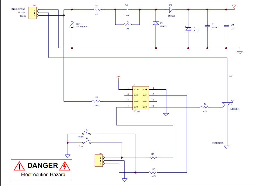
Assistance is required to modify a light dimmer circuit connected to a PIC12C508 microcontroller. This circuit is designed for the... The light dimmer circuit utilizing the PIC12C508 microcontroller serves to control the brightness of a light source through pulse width...
In the image above, Oscium's iMSO-104 oscilloscope is measuring the output waveform of an infrared receiver (IR Rx). The iPad and iMSO serve as the oscilloscope to measure the receiver's output signal as the alignment between the transmitter and...
This is a high quality power supply with a continuously variable stabilised output adjustable at any value between 0 and 30VDC. The circuit also incorporates an electronic output current limiter that effectively controls the output current from a few...
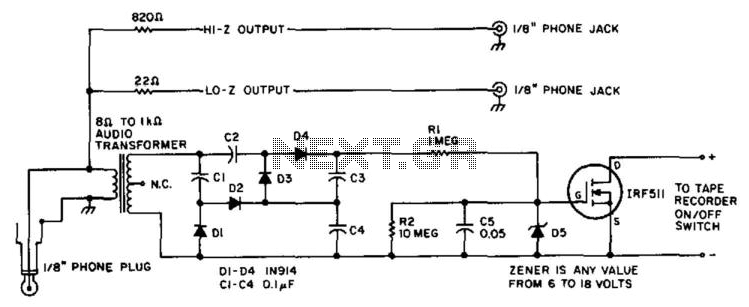
A tape recorder can be controlled by rectifying the audio input and driving an IRF511 power MOSFET to switch the tape recorder on when audio is present. This circuit was used with a communications receiver to record intermittent transmissions,...

This is a simple touch switch circuit where the 555 timer is configured as a one-shot multivibrator triggered by touching the touch terminal. In monostable mode, the timer generates a fixed pulse of approximately 4 seconds whenever the trigger...

A microcontroller is a single-chip computer that includes internal RAM, ROM, timers, counters, interrupt circuitry, I/O ports, analog comparators, serial USARTs, analog-to-digital converters, watchdog timers, and a RISC architecture. Unlike microprocessors, which require additional components such as RAM and...