
Seven-segment LED display circuit diagram of a counter
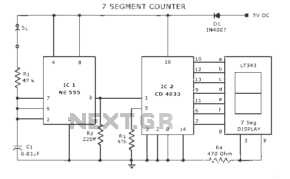
The display counter circuit employs the CD4033 integrated circuit, which is specifically designed for driving seven-segment displays. The IC counts up on each pulse received at its input pin, effectively converting the pulse frequency into a visual representation through the connected seven-segment display. The astable multivibrator circuit, constructed from the 555 timer IC, generates a continuous square wave signal that acts as the trigger for the CD4033. The frequency of this signal can be adjusted by modifying the resistor and capacitor values in the 555 timer configuration, allowing for control over the counting speed.
The seven-segment display consists of individual LEDs arranged to form digits from 0 to 9. Each segment of the display is activated by specific outputs from the CD4033, which correspond to the current count. The LT543 diode ensures that current flows in the correct direction, protecting the circuit from reverse polarity conditions that could potentially damage the components. The inclusion of switch S1 provides an additional layer of safety by allowing the user to disable the circuit when not in use, thereby preventing unintended counting or circuit activation.
This display counter circuit can be adapted for various applications, including educational demonstrations, digital timers, and scoring systems. The flexibility of the CD4033 and the astable multivibrator configuration makes it suitable for creating a range of counting and timing devices. The provided parts list and circuit diagrams facilitate easy replication and experimentation, enabling users to explore additional functionalities or modifications to enhance the circuit's performance.Display counter circuit Explanation Here is a circuit diagram of a seven-segment on the counter IC CD 4033. This counter circuit in which a counter to show the progress increased attractiveness for use with some of the various circuits. Astable multivibrator IC 555 wired northeast CD 4033.For each trigger pulse, CD 4033 CD 4033 count.The progress output seven segment LED display shows counting.Diode LT543.Switch S1 is used to prevent accidental starting of D1 polarity inversion risk.
Seven parts list and circuit diagrams. Some circuits, you might want to see. Displaying 1, the static 0-9 2, up / down counter circuit 3, a digital timer circuit 4, long duration timer circuit 5, scoring circuit.
Related Circuits

The circuit illustrated here demonstrates that, despite advancements in components and technology, it remains possible to design effective and intriguing circuits. This design utilizes two well-known transistors, the BF256C and the BF494. Along with the necessary resistors and capacitors,...
Here is a deluxe version of the simple charge rate limiter, using the same idea but with the ability to charge two packs simultaneously from a single wall charger. For circuit description and parts list, see the simple charger...
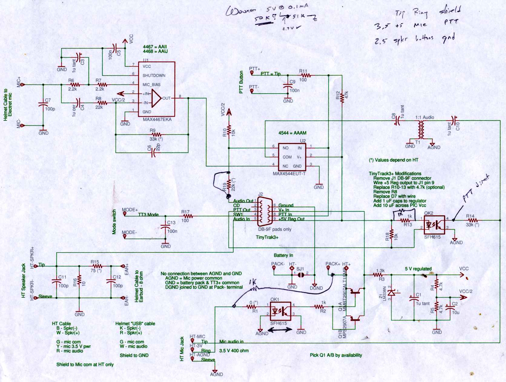
Connect the Byonics TinyTrak 3+ GPS modem, helmet earbud/mic, and external battery pack to the Z-1A, which is incompatible with the Wouxun. The KG-UV3D utilizes the Kenwood HT interface with a single ground for mic, speaker, and PTT functions,...
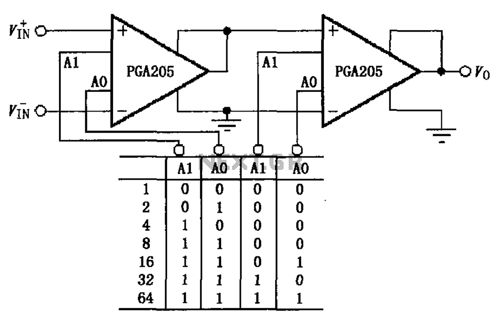
A binary gain step circuit is illustrated using the PGA205, which has a gain range of 1 to 64. The circuit employs two PGA205 devices in cascade, resulting in a total gain that is the product of the individual...
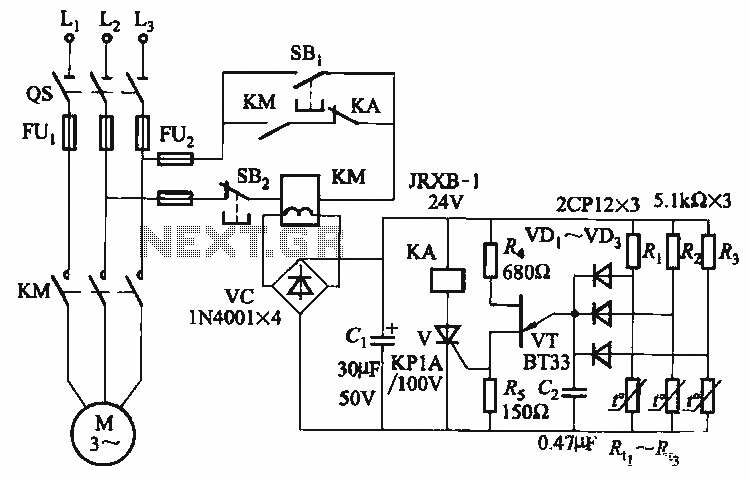
The thyristor control circuit includes a bridge circuit designed to regulate the temperature in the contactor coil KM, along with a secondary winding that functions as a power protection device. It comprises a thermistor (R:., Rt3) and a resistor...
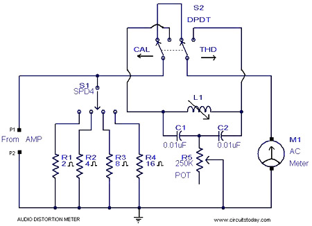
This is a simple 1 kHz audio distortion meter designed to measure the Total Harmonic Distortion (THD) on any load at any output power. The circuit allows for the selection of load impedances of 2, 4, 8, or 16...