
The use of self-induced emf achieve instant protection circuits

The circuit operates effectively as a protective measure against sudden power interruptions. The self-induced emf generated by the motor during a power loss is crucial for maintaining operation continuity. The use of diode VD is essential to prevent backflow of current, ensuring that the relay KA receives the necessary power to activate without interference from other circuit components.
Upon the loss of power, contact KM disengages, but the inertia of the motor allows it to continue rotating momentarily. The auxiliary contact, which remains closed during this event, permits the self-induced emf to energize the relay KA. This relay serves as a crucial link in the circuit, allowing the motor to remain operational for a brief period despite the absence of external power.
Once the power supply is restored, the contactor KM is re-energized, engaging its self-locking feature. This mechanism ensures that the motor is automatically reconnected to the power supply without the need for manual intervention, thus enhancing operational efficiency and reducing downtime. The design is particularly beneficial in applications where uninterrupted operation is critical, such as in industrial machinery and automated systems.
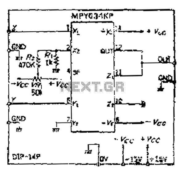
Overall, this circuit configuration effectively combines inertia, self-induced emf, and relay mechanisms to safeguard against power failures, ensuring that essential systems remain operational or can quickly resume operation after a power interruption. Circuit shown in Figure 3-73. The line is to use the power of instantaneous power failure, the self-induced emf generated by the motor to implement now instant shutdown protect ion. When momentary power outage, contact KM loss of power release, power machine for inertial rotation, while KM normally closed auxiliary contact is closed, the motor V, W and white self-induced emf through diode VD to the DC relay is powered KA. KA is energized, the normally open contact closure, if it when the power supply has been restored, the contactor KM obtain electric suction combined self- locking, the motor re-connect the power running.
Related Circuits
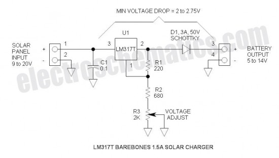
This is a simple and cost-effective solar battery charger that can be constructed by hobbyists. It has some limitations compared to other similar controllers, but it also provides several benefits. While primarily designed for charging lead-acid batteries, it can...
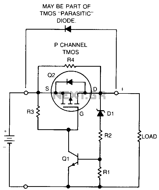
If a NiCad battery is discharged to the point where the lowest capacity cell becomes fully discharged and reverses polarity, that cell will typically short internally and become unusable. To prevent this type of damage, this circuit detects a...
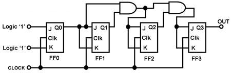
The circuit in Figure 1 is a 4-bit asynchronous counter, also known as a ripple counter. It consists of four J-K flip-flops with their J and K inputs connected to logic 1. This configuration causes the output of each...
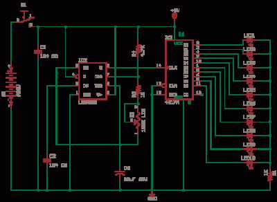
The 555 Astable generates a clock for this circuit, functioning as an oscillator that produces a square wave output at pin 3. This output is counted by the CD4017 decade counter, which creates a running lights effect. The CD4017...
Although the inputs are differential, the right amplifier has a bias current greater than 800 nA. Therefore, the input coupling capacitor should be considered. It is important to note that the resistance value on the input side should also...
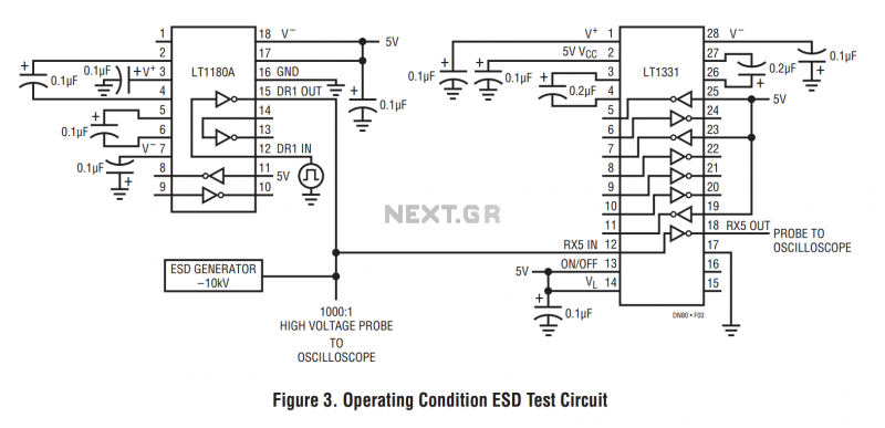
The machine model, commonly used for ESD testing in Japan, is a more severe ESD test. This model simulates metallic contact between the device under test and a charged body. The source capacitor is 200pF with no limiting resistor....