
digital counter circuits
The 4-bit asynchronous counter, or ripple counter, operates on the principle of sequential toggling of J-K flip-flops. In this configuration, the first flip-flop toggles its output state with each incoming clock pulse due to its J and K inputs being held high. This output then serves as the clock input for the next flip-flop, creating a cascading effect. Each subsequent flip-flop toggles based on the output of the previous one, resulting in a binary count that propagates through the flip-flops, hence the term "ripple." The counter counts up from 0 to 15 in binary (0000 to 1111) before resetting back to 0.
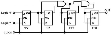
In contrast, the 4-bit synchronous counter achieves its counting mechanism through simultaneous clocking of all flip-flops. The first flip-flop still has its J and K inputs tied to logic 1, allowing it to toggle with each clock pulse. However, the second flip-flop's inputs are derived from the output of the first flip-flop, leading to a toggle rate that is half that of the first flip-flop. This pattern continues with each subsequent flip-flop being controlled by an AND gate that combines the outputs of the two preceding flip-flops, ensuring that the toggling continues at a halved rate, thus maintaining the binary counting sequence.
This synchronous design minimizes the propagation delay issues associated with asynchronous counters, making it more suitable for applications requiring precise timing and synchronization. The overall architecture of both counters illustrates fundamental principles of digital electronics, particularly in the use of flip-flops for counting and state storage.The circuit in Figure 1 is that of a 4-bit asynchronous counter, also known as a `ripple counter`. It consists of 4 J-K flip-flops whose J and K inputs are tied to logic `1`. This connection causes the output of each J-K flip-flop to toggle every time it gets a clock pulse. By using the output of the previous flip-flop to clock the next flip-flop, a `rippling` effect is achieved causing the flip-flops to count in binary fashion. The circuit in Figure 2 is that of a 4-bit synchronous counter. It consists of 4 J-K flip-flops, all of which are clocked at the same time, hence the name `synchronous counter`. Thus, the toggling of the output of the flip-flops in this counter depends on the states of their J and K inputs.
Recall that the J-K flip-flop`s output will only toggle when both J and K are `high`. The first flip-flop (lease-significant bit) of a synchronous counter has its J and K inputs directly tied to logic `1`. This causes its output to toggle automatically every time it gets a clock pulse. The second flip-flop`s J and K inputs are directly tied to the output of the first flip-flop. Thus, even if they get clocked at the same time, the second flip-flop will only toggle half the times as the first one.
The subsequent flip-flops` J and K inputs are tied to an AND gate whose inputs are tied to the outputs of the last two flip-flops before it. This ensures that each of these flip-flops will toggle at half the rate as the flip-flop before it, even if they are all clocked at the same time.
🔗 External reference
Related Circuits
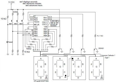
A digital clock project utilizing the PIC16C54 microcontroller can be constructed using the provided circuit diagram. This electronic project features a straightforward time-of-day clock that includes four seven-segment LED displays and three input switches, along with an additional reset...
An audio test oscillator circuit typically produces a square wave if the oscillation frequency is low enough in relation to the amplifier's bandwidth. This circuit features a crystal-controlled oscillator designed for low-frequency sine wave generation, characterized by low distortion,...
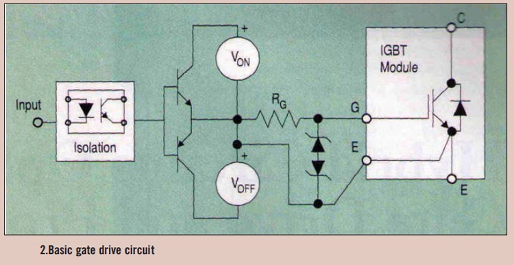
High power IGBT modules utilize hybrid integrated circuit (IC) gate drives that incorporate protection circuits, which implement desaturation detection or real-time control. High power Insulated Gate Bipolar Transistor (IGBT) modules are essential components in various high-efficiency power conversion applications, such...
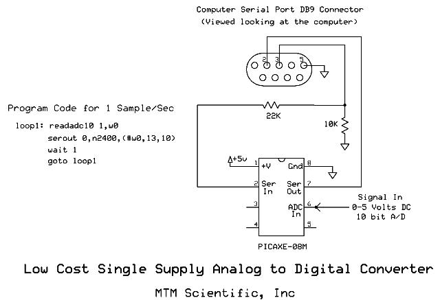
Collecting and storing experimental data presents a common challenge for hobbyists. A widely used method involves utilizing a device that converts analog data into digital format and stores the information on a computer. These devices are known as A/D...

The circuit described is a crystal oscillation circuit using a CM OS inverting configuration, designed to ensure accurate operation. It employs a BCD counter (IC2) capable of achieving a maximum oscillation frequency of 2 MHz, which is 100 times...
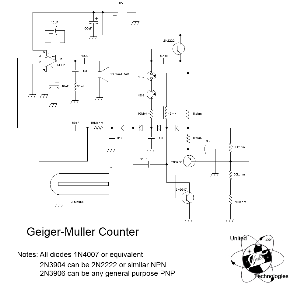
The basic charging circuit generates over 500V, depending on the inductor, component leakage, and other factors. The current output is limited by a 10 MΩ resistor, maintaining a short-circuit current under approximately 60 µA, making this project relatively safe....