
Intermittent one start and stop cycle control circuit
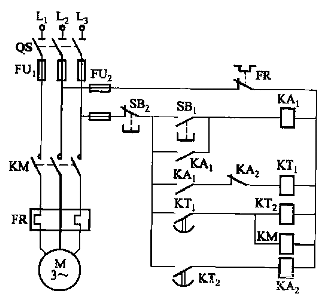
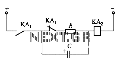
The circuit utilizes two time relays to provide precise control over the motor's operational cycles. Relay KTi is responsible for initiating the motor's operation, while relay KTz is tasked with managing the downtime period. This configuration allows for effective automation of the motor control process, ensuring that the motor runs for a predetermined duration before switching off, thereby preventing overheating and excessive wear.
The time relays can be adjusted to set specific on and off durations, allowing for flexibility in various applications. The relays are typically connected in a manner that ensures the motor receives power only during the active phase dictated by KTi. Once the set time elapses, KTi deactivates, and the circuit transitions to the downtime phase controlled by KTz, ensuring that the motor remains off for the specified period.
This arrangement is particularly useful in applications where motors are required to operate intermittently, such as in conveyor systems, pumps, or HVAC systems. The use of time relays enhances the efficiency of the motor operation, reduces energy consumption, and prolongs the lifespan of the motor by minimizing unnecessary run time.
In summary, the circuit demonstrated in Figure 3-76 effectively employs two time relays to control motor operation and downtime, providing a reliable and efficient solution for automated motor management. Circuit shown in Figure 3-76. It uses two time relay to achieve control. KTi and KTz control the motor running and downtime.
Related Circuits
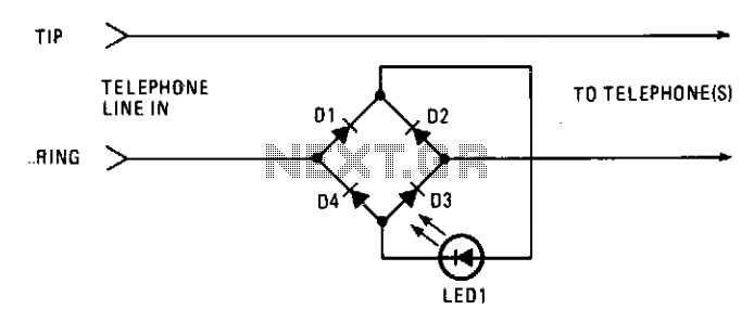
This circuit operates as a line-current sensor and can be connected in series with any of the phone lines. To indicate an "in use" status for all phones on a single line, it must be connected in series with...
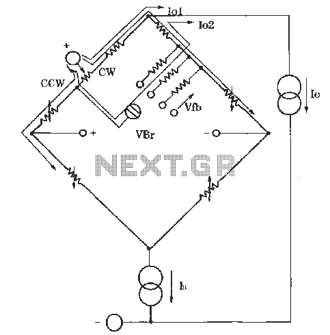
The circuit for zero and span adjustment consists of a feedback resistor network and a differential pressure sensing bridge measuring circuit. A constant current source, IO, represents the output current. The resistances of the four bridge arms are R1S,...
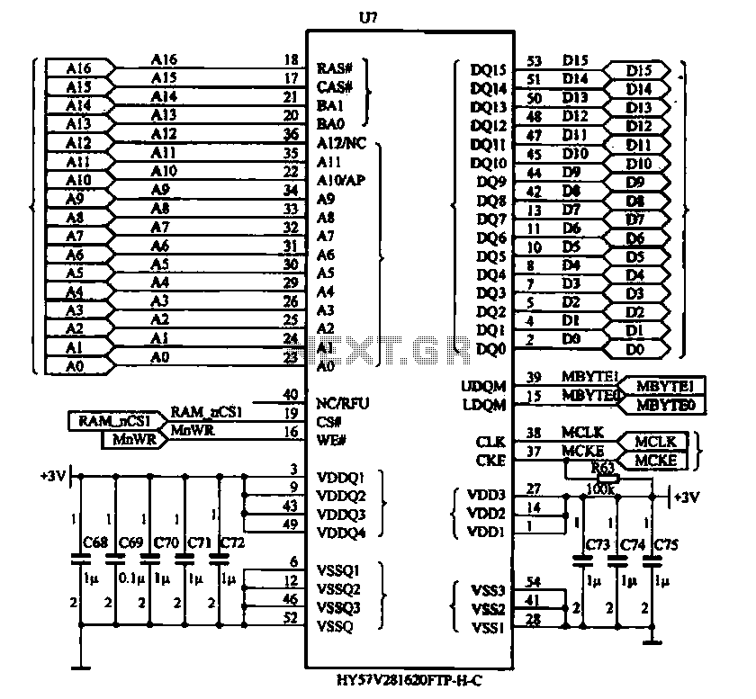
The Newman MP4 machine features three types of memory: data memory (U7), program memory (U8), and user memory (U9). Data memory is utilized for storing operational data, while program memory holds the machine's work program. User memory is designated...
To fulfill the requirements of a control loop, it is often necessary to utilize an electromagnetic relay or a transistor relay to either accelerate or delay an action, thereby forming an acceleration or delay circuit. The circuit depicted in...
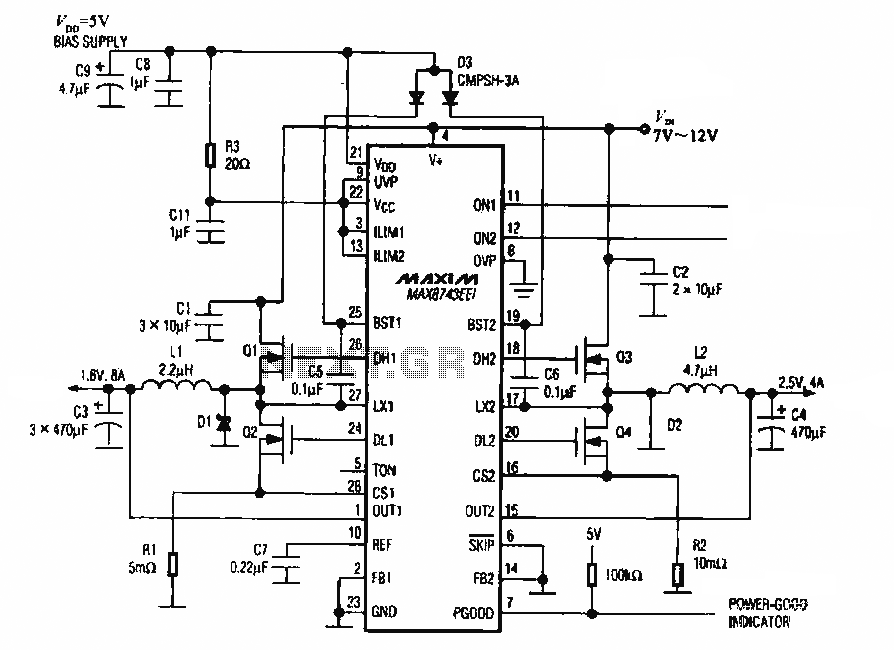
The circuit utilizes the MAX8743 chip for a laptop chipset power supply. It demonstrates the conversion of a 5V power supply into +2.5V and +1.8V outputs. The MAX8743 is a highly integrated power management solution designed specifically for laptop chipsets....
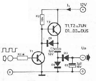
Voltage inverter circuit design electronic project using few electronic components The voltage inverter circuit is a fundamental electronic project that converts direct current (DC) to alternating current (AC). This circuit is particularly useful in applications where AC voltage is required...
Warning: include(partials/cookie-banner.php): Failed to open stream: Permission denied in /var/www/html/nextgr/view-circuit.php on line 713
Warning: include(): Failed opening 'partials/cookie-banner.php' for inclusion (include_path='.:/usr/share/php') in /var/www/html/nextgr/view-circuit.php on line 713