
PTC phase asynchronous motor circuit protection one
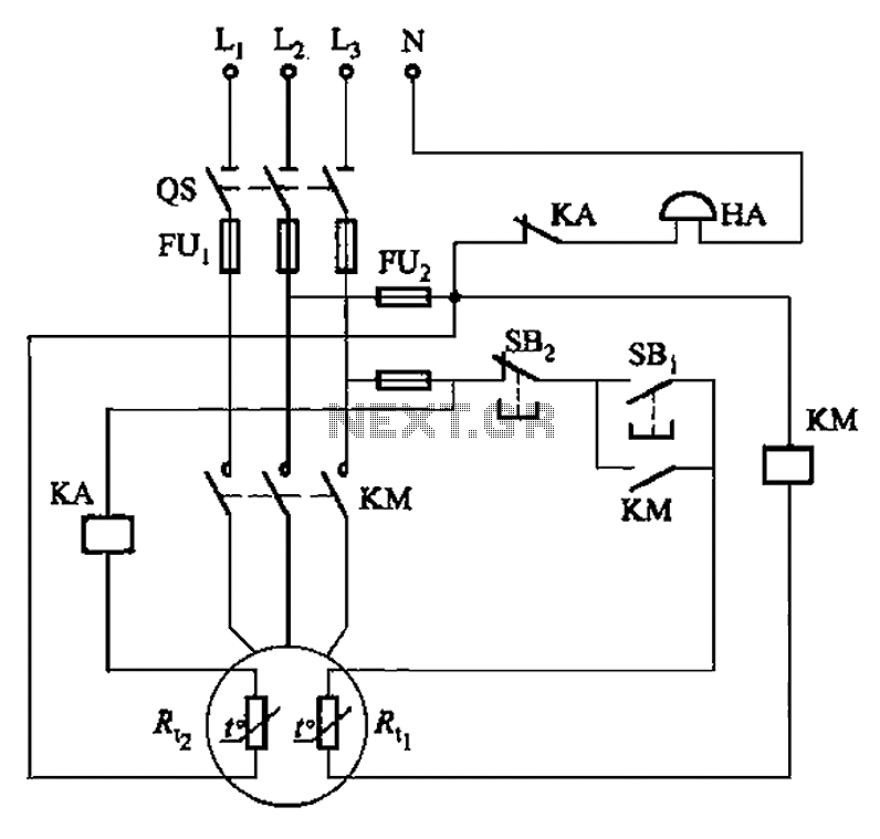
The circuit in question integrates two thermal resistors to monitor temperature changes and provide protective and alert functions. The first thermal resistor, Rc, is designed to activate when excessive current or temperature is detected, thereby protecting the circuit from potential damage due to overload conditions. This resistor is typically connected in series with the load, allowing it to sense the thermal rise caused by increased current flow. When the temperature exceeds a predetermined threshold, Rc triggers a mechanism, such as a relay or a circuit breaker, to disconnect the load and prevent overheating.
The second thermal resistor, Rt, is utilized as an alarm system. It is calibrated to respond to different temperature levels than Rc, allowing it to signal when the system is approaching critical operational limits. This can be achieved by connecting Rt to a microcontroller or an alarm circuit that activates a visual or audible alert when the temperature reaches a specific set point. The alarm provides an early warning to operators, enabling timely intervention before any damage occurs.
In terms of configuration, both thermal resistors should be selected based on their resistance-temperature characteristics, ensuring they respond accurately to the expected temperature range of the application. The placement of these resistors within the circuit is crucial; they should be positioned where they can effectively sense the thermal variations without being influenced by external factors. Proper calibration and testing of the thresholds for both Rc and Rt are essential for reliable operation.
Overall, this circuit design effectively combines overload protection with an alarm system, enhancing the safety and reliability of the electronic device it serves. Circuit shown in Figure 4-2. It uses two thermal resistors, a (Rc,) is used as overload protection, another (Rt :) used as an alarm.
Related Circuits
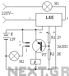
The device circuit operates as illustrated in Figure 11. Power outages are a common occurrence, but in certain situations, maintaining power is critical, such as during ongoing surgeries. The circuit employs a simple design that is fully automated. When...
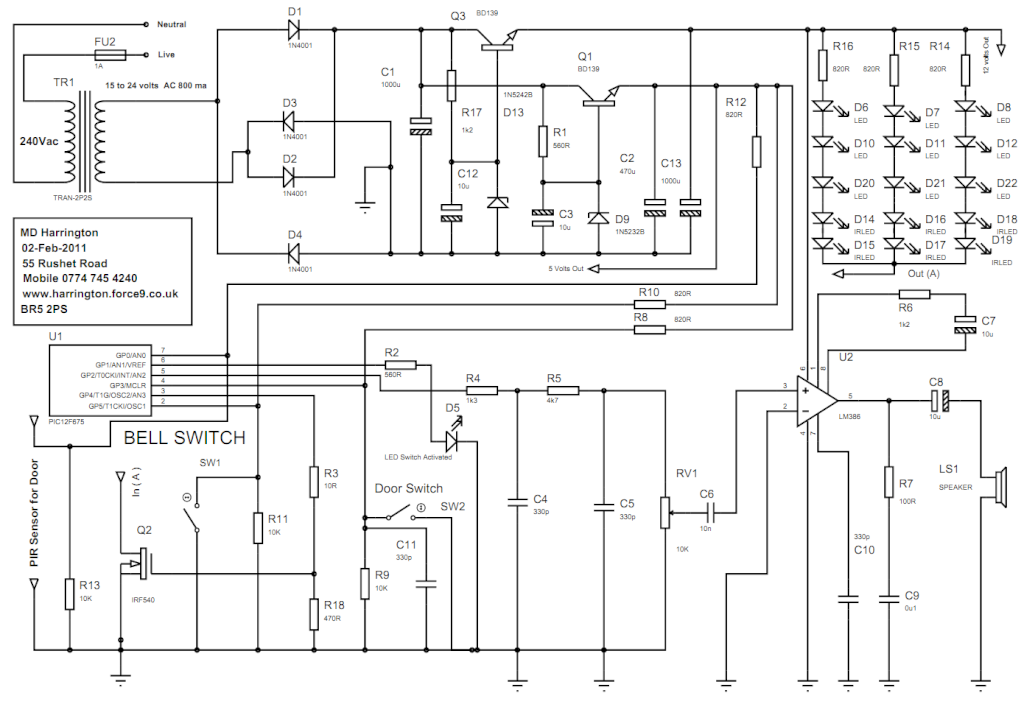
The circuit consists of a power supply formed by TR1, Q3, D13, Q1, and D9. This power supply provides both the 12-volt and 5-volt rails required for the microcontroller. The power supply circuit is essential for ensuring stable voltage levels...
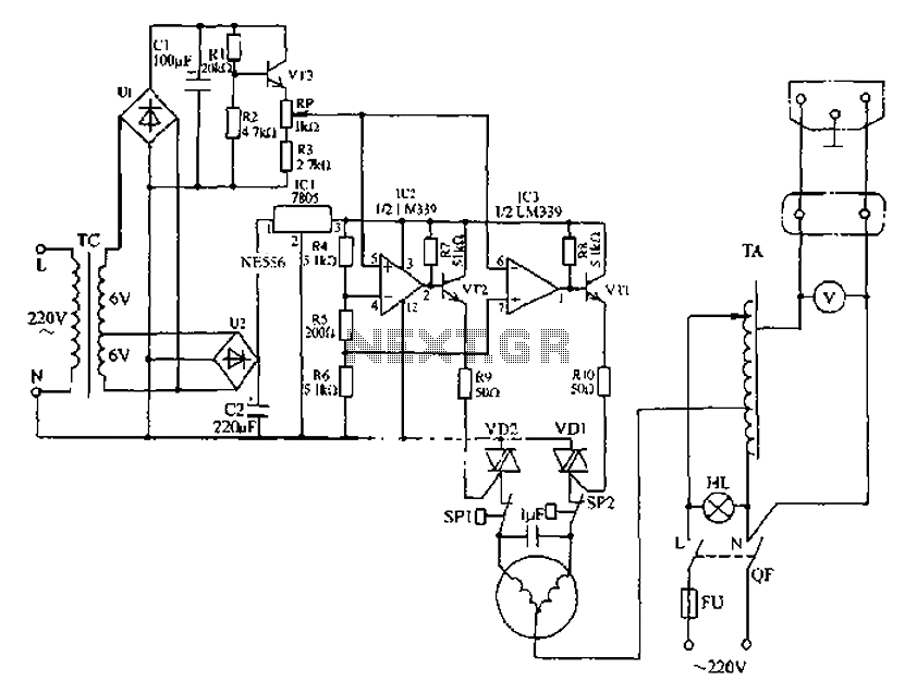
Automatic AC voltage regulator circuit The automatic AC voltage regulator circuit is designed to maintain a stable output voltage despite fluctuations in the input voltage. This circuit is essential for protecting sensitive electronic devices from voltage variations that can lead...

2 versions of the equalization circuit, the first having 6 dB less insertion loss than the other. However, some may not be able to find a 0.68 microfarad capacitor. The second version uses a more common 0.22 microfarad capacitor....

The LED meter circuit is more compact and simpler than its analog equivalent, making it a common choice in audio equipment. This circuit utilizes the LM3915 integrated circuit (IC) and operates in a logarithmic mode. It comprises a single...

Here is a small FM transmitter circuit designed for desktop or laptop use, allowing users to enjoy movies and music from a distance. This USB-powered FM transmitter connects to a computer or MP3 player and broadcasts on a tape...
Warning: include(partials/cookie-banner.php): Failed to open stream: Permission denied in /var/www/html/nextgr/view-circuit.php on line 713
Warning: include(): Failed opening 'partials/cookie-banner.php' for inclusion (include_path='.:/usr/share/php') in /var/www/html/nextgr/view-circuit.php on line 713