
LED Audio VU Meter Circuit

The LED meter circuit based on the LM3915 IC is designed for efficient and effective audio level monitoring. The LM3915 is a bar graph/LED dot display driver capable of displaying audio levels with high accuracy. Its logarithmic response is particularly suited for audio applications, as human perception of sound intensity is logarithmic in nature.
The circuit operates by receiving an audio input signal, which is then processed by the LM3915. The IC translates the input voltage into a corresponding output that drives the LEDs. In normal operation, the first eight LEDs (L1 to L8) illuminate to indicate audio levels, providing a visual representation of the signal strength. When the audio level exceeds a predetermined threshold, the last two LEDs (L9 and L10) light up in red, signaling an overload condition. This feature is crucial for preventing distortion and potential damage to audio equipment.
The inclusion of diode D3 ensures that the voltage supplied to the LEDs is stable and not subject to fluctuations that could arise from filtering. This allows for a more responsive display, as the LEDs can react quickly to changes in the audio signal without the lag that can occur with fully smoothed DC supplies. Capacitor C1 plays a vital role in maintaining the stability of the circuit by preventing oscillations that could lead to erratic LED behavior.
The power supply design, utilizing a 15-0-15 transformer, is optimized for low power consumption. The transformer provides the necessary AC voltage, which is then rectified and regulated to supply the LM3915 and the LEDs. The choice of a small transformer is justified by the low peak current requirement of 120mA DC, making the circuit energy-efficient.
Overall, this LED meter circuit serves as an effective tool for visualizing audio levels in various applications, from home audio systems to professional sound equipment, ensuring that users can monitor audio performance accurately and avoid overload situations.The LED meter circuit is simpler and smaller than its analogue counterpart, and is very common in audio equipment. This circuit is based on LM3915 IC and uses the logarithmic version. This circuit is using a single IC and a few discrete components. The extra diode (D3) is included to ensure that the DC to the LEDs is almost unfiltered. C1 is inclu ded to make sure the IC does not oscillate, and is not a filter capacitor. This allows a higher LED current with lower dissipation than would be the case if the DC were fully smoothed, and full smoothing would also require a much larger capacitor. This is the figure of the LED audio VU meter circuit; How is this circuit work We will explain with simple ways.
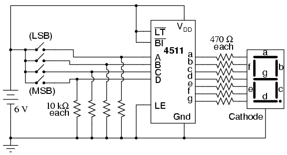
L1 to L8 will normally be green (normal operating range) and L9 and L10 should be red (indicating overload). This gives a 6dB overload margin when the unit is calibrated as described below. As shown, full scale sensitivity (with VR1 at maximum) is 12 Volts peak (approximately 8. 5 volts RMS). This is designed for direct connection to the speaker output of an amplifier, but is still suitable for use with preamps if the sensitivity is changed.
Power comes from a 15-0-15 transformer (connected to AC1-Com-AC2). You can generally use the smallest one available, as average power is quite low. The peak current is about 120mA DC, so a 5VA transformer will be sufficient to power two meter circuits. One 15V winding goes to the terminal AC1, the other goes to AC2 and the centre tap is connected to Com (Common).
🔗 External reference
Related Circuits
The differential thermometer utilizes two probes to display the temperature difference between them instead of indicating the precise temperature. It employs a conventional meter as an indicator and has a total range of -10°C to 20°C. The differential thermometer operates...
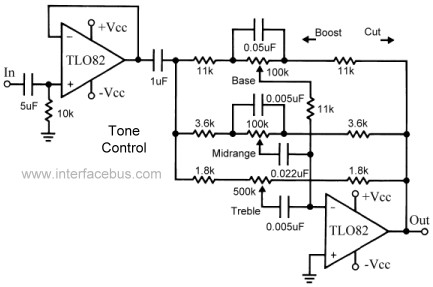
This topic continues the coverage of audio tone controls. The first entry started with a passive tone control circuit using different RC filter configurations and introduced an active filter. The second entry showed a fully designed 2-band active tone...
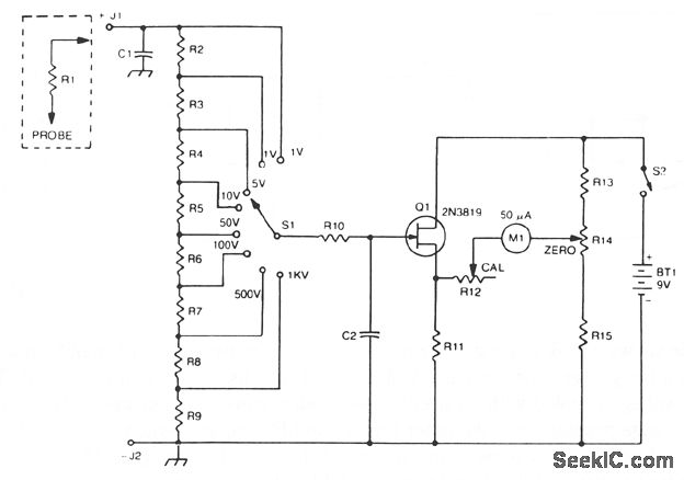
The 2N3819 FET serves as a solid-state voltage output meter (VOM). In this configuration, the 2N3819 functions as a cathode follower. The bias offset, or meter null, is achieved using resistors R14 and R12, while the full-scale calibration is...
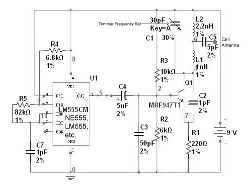
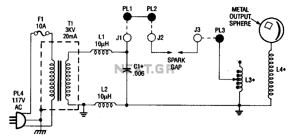
A cell phone jammer is an electronic device designed to obstruct the transmission of signals between a cell phone and its nearby base station. By transmitting on the same frequency as cell phones, the jammer generates significant interference, disrupting...
Digital circuits are circuits that handle signals restricted to binary states of zero and a maximum value. This is in contrast to analog circuits, where signals can vary continuously within the limits set by power supply voltage and circuit...
This is a circuit diagram for a simple doorbell. The circuit can be assembled indoors, while the switch should be placed outside, making it easily noticeable for visitors. The operation of this circuit is similar to a previous project. The...
Warning: include(partials/cookie-banner.php): Failed to open stream: Permission denied in /var/www/html/nextgr/view-circuit.php on line 713
Warning: include(): Failed opening 'partials/cookie-banner.php' for inclusion (include_path='.:/usr/share/php') in /var/www/html/nextgr/view-circuit.php on line 713