
KL-25 type automatic thyristor excitation device circuit
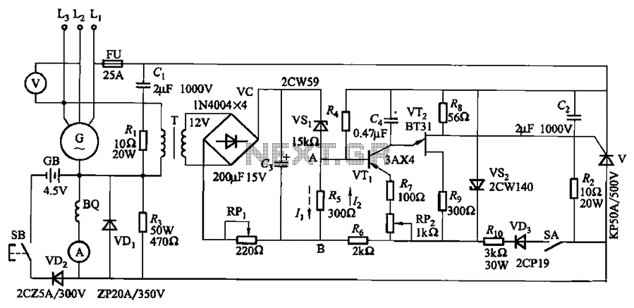
The circuit in Figure 7-32 is structured to facilitate the effective regulation of excitation in synchronous generators, which are commonly utilized in various power generation applications. The excitation device operates optimally within specified voltage and power limits, ensuring reliability and efficiency in operation.
The SB Kai Lai button functions as a manual trigger for initiating the self-excitation process. When the prime mover accelerates the generator to its rated speed, pressing this button engages the excitation system, allowing the generator to generate the necessary voltage through self-stimulation. This self-excitation process is critical for maintaining the voltage stability of the generator under varying load conditions.
The RPi manual regulator potentiometer is a key component that provides operators with the capability to fine-tune the output voltage of the generator. By adjusting this potentiometer, the operator can either increase or decrease the voltage output, allowing for real-time responses to load changes or system requirements. This feature is particularly important in applications where voltage stability is crucial for system performance.
Furthermore, the RP2 sensitivity adjustment allows for greater control over the excitation system's response to fluctuations. In scenarios where excitation oscillation is detected, reducing the sensitivity can help stabilize the system, preventing potential damage or inefficiencies. This adaptability is essential in maintaining optimal generator performance.
The shutdown procedure, controlled by switch SA, ensures that the excitation system can be safely deactivated when required. By interrupting power to the trigger circuit, the generator can be de-excited without risking damage to the system, thereby enhancing operational safety and longevity.
Overall, this circuit design provides a comprehensive solution for managing the excitation of synchronous generators, integrating manual controls and sensitivity adjustments to optimize performance and ensure stability in various operational contexts. Circuit shown in Figure 7-32. The excitation device is suitable for terminal voltage of 400V, a capacity of less than 75kW synchronous generator motor for automatic adjustment of excitation. Figure, SB Kai Lai button when the generator is pulled to the rated speed of the prime mover, short press the SB, to make electricity to build several self-stimulation voltage; RPi manual regulator potentiometer, RPi reduced ( or increase), the generator voltage drop (or rise Fan). Adjusting RP2, adjustable sensitivity of the device. If the excitation oscillation, can reduce sensitivity try. Shutdown, the switch SA cutoff, trigger circuit loses power, you can achieve generator de-excitation.
Related Circuits

This circuit is designed for general-purpose use with a large LED display utilizing SPI serial interfacing. It employs a serial-in-parallel-out shift register, specifically the 74HC595, to receive serial data from a microcontroller board. The schematic wiring indicates that SER...
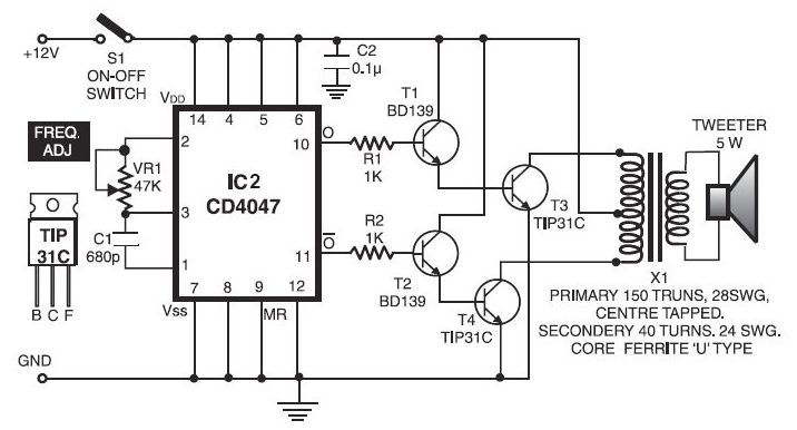
The electronic dog repellent circuit diagram below is a high-output ultrasonic transmitter primarily intended to act as a dog and cat repeller. The electronic dog repellent circuit utilizes a high-frequency ultrasonic transmitter to emit sound waves that are unpleasant to...
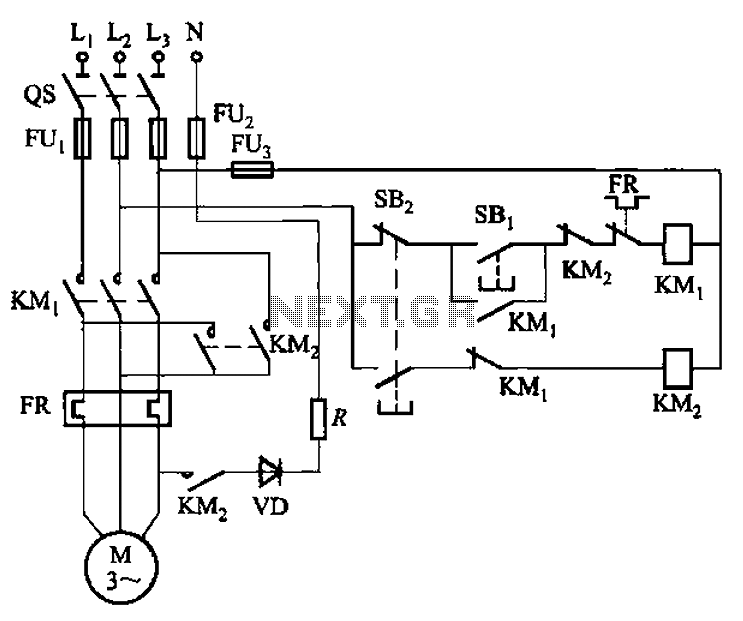
The circuit shown in Figure 3-139 utilizes a rectifier diode brake for neutral grounding in a three-phase, four-wire power supply system. The circuit employs a rectifier diode configuration to achieve effective neutral grounding, which is crucial for maintaining system stability...
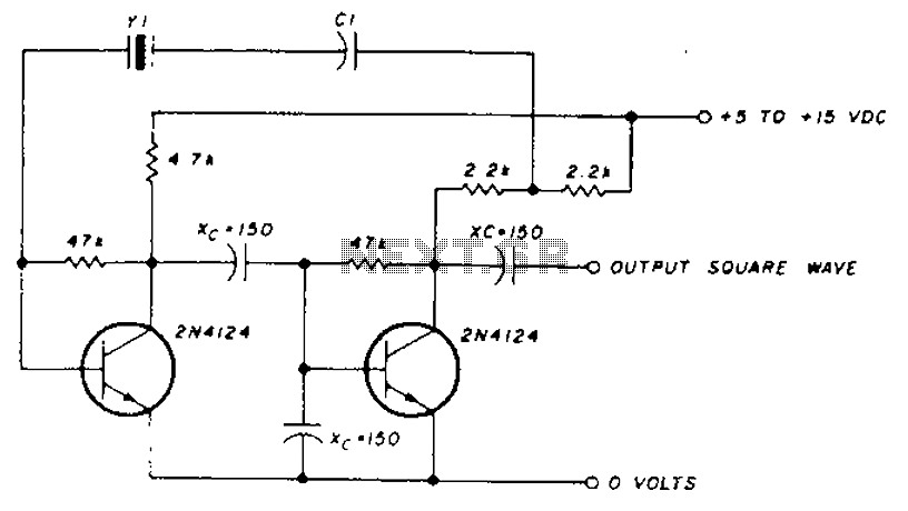
A transistor in series with capacitor C1 can be utilized to adjust the oscillator output frequency. The frequency may vary with changes in capacitance ranging from 20 pF to 0.01 µF, or as determined by the tuning capacitor. The...
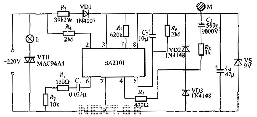
The BA2101 is a dimming controller utilizing an ASIC to create a barrel of light touch stepping. It is a non-constant lamp suitable for heir light. Each touch on the electrode sheet M can adjust the lamp brightness through...
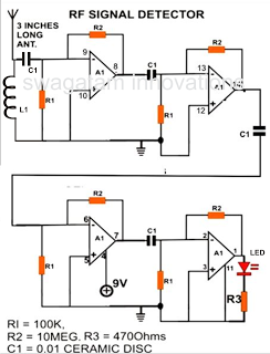
A simple electronic circuit project is presented that can be constructed by any school student for display at a school science fair. The proposed circuit is a high-gain operational amplifier (op-amp) amplifier designed to detect the slightest RF disturbances...
Warning: include(partials/cookie-banner.php): Failed to open stream: Permission denied in /var/www/html/nextgr/view-circuit.php on line 713
Warning: include(): Failed opening 'partials/cookie-banner.php' for inclusion (include_path='.:/usr/share/php') in /var/www/html/nextgr/view-circuit.php on line 713