
Dog Repellent Circuit
The electronic dog repellent circuit utilizes a high-frequency ultrasonic transmitter to emit sound waves that are unpleasant to dogs and cats, effectively deterring them from approaching certain areas. The core component of this circuit is typically a piezoelectric ultrasonic transducer, which converts electrical signals into ultrasonic sound waves that are inaudible to humans but can be perceived by animals.
The circuit may include a microcontroller or timer IC to control the operation of the transmitter, allowing for the adjustment of the frequency and duration of the ultrasonic pulses. A power supply, often a battery or a DC power adapter, provides the necessary voltage and current for the circuit operation. Additional components such as resistors, capacitors, and diodes may be included to filter and stabilize the output signal.
When activated, the circuit generates ultrasonic waves at a frequency often ranging from 20 kHz to 65 kHz. This frequency range is effective in repelling dogs and cats, as it falls within their hearing range but is above the threshold of human hearing. The design may also incorporate a motion sensor to trigger the ultrasonic waves only when an animal is detected, thereby conserving power and enhancing the efficiency of the device.
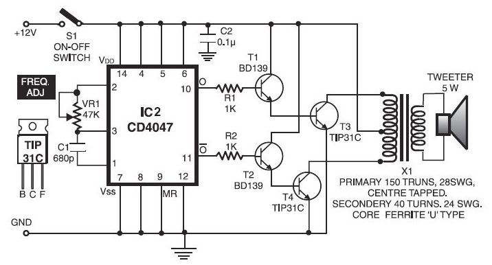
Overall, the electronic dog repellent circuit is a practical solution for managing unwanted animal presence in specific areas, leveraging ultrasonic technology to provide a humane deterrent.The electronic dog repellent circuit diagram below is a high output ultrasonic transmitter which is primarily intended to act as a dog and cat repeller, wh.. 🔗 External reference
Related Circuits
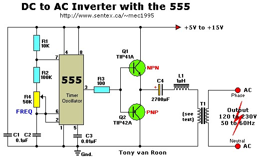
This simple 12V DC to 220V AC inverter circuit generates an AC output at line frequency and voltage. The 555 timer is configured as a low-frequency oscillator, adjustable over the frequency range of 50 to 60 Hz via the...
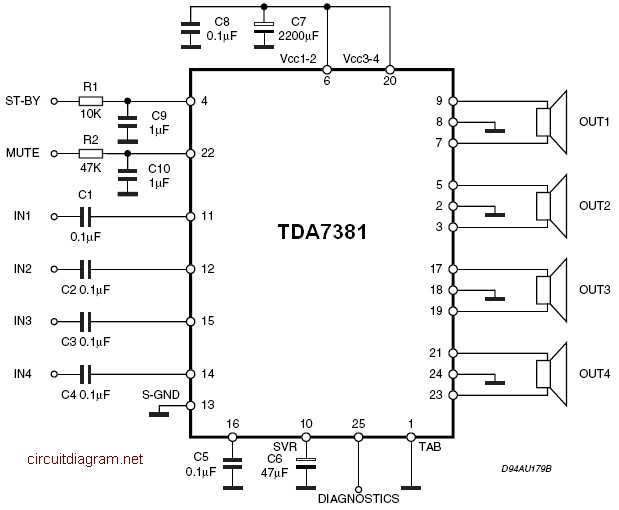
The amplifier is a quad amplifier circuit (amplifier with four inputs and four outputs) based on the TDA7381. This amplifier is designed for car audio systems, but it can also be utilized for other applications. The circuit has a...

Lithium-based (Li+) batteries are increasingly used in portable devices due to their favorable characteristics. However, they are often in limited supply, leading to long lead times unless a preferred-customer status is established with manufacturers. Consequently, a backup alternative to...
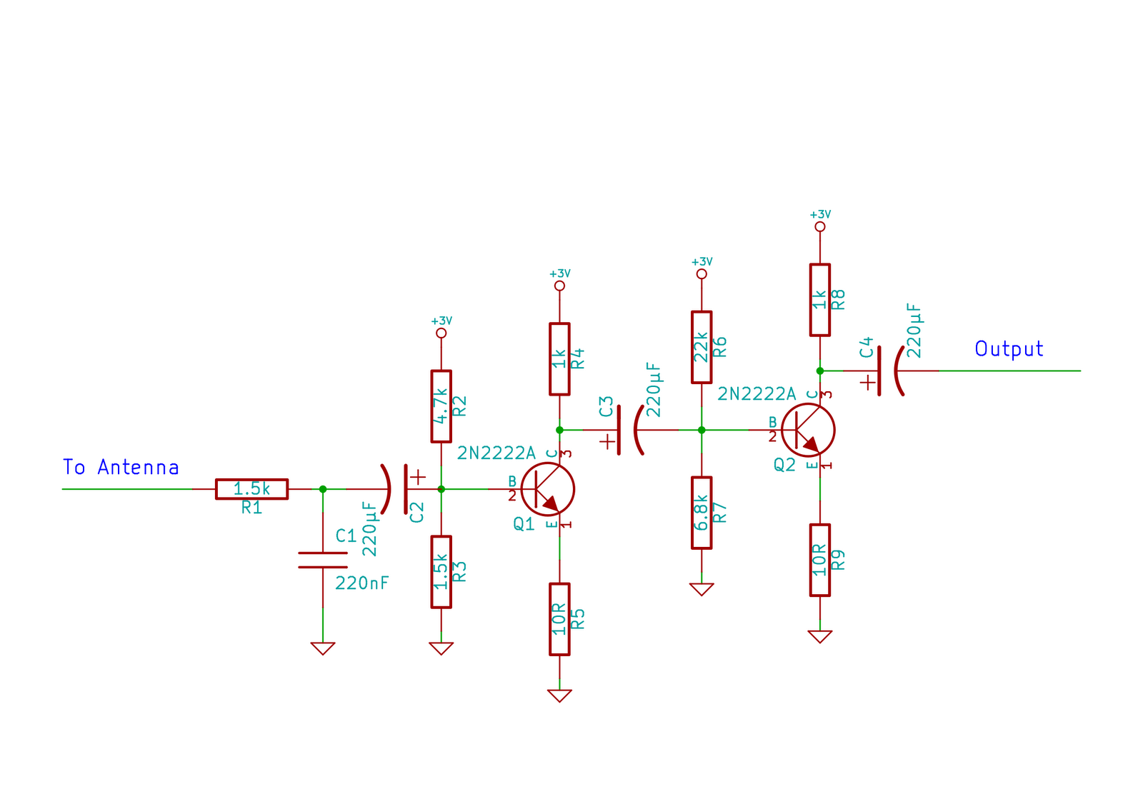
This circuit does not function as effectively as it could. It was created when the designer had a limited understanding of circuit design. An improved schematic will be developed and posted later, featuring a better design. The schematic indicates...
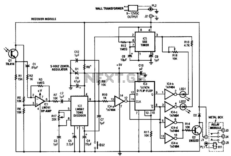
Useful for A/B control, the IR receiver shown controls a relay from an infrared beam that has a pulsed tone-modulated signal. Q1 is the photo receptor feeding op amp IC1, tone decoder IC2, and flip-flop IC3. IC5 turns off...

This design circuit features a simple, cost-effective amplitude-stabilized phase-shift sine wave oscillator that requires one integrated circuit (IC) package, three transistors, and operates from a single power supply. The circuit incorporates an RC network configured for phase shift, oscillating...