
mobile phone charger circuit 12
The circuit design for the mobile charger comprises several key components working in conjunction to facilitate efficient charging of mobile devices. The core of the circuit consists of four 1.5-volt pen cells connected in series, forming a battery pack that provides a total voltage of 6 volts. This configuration is beneficial for charging devices that typically require a voltage of around 3.6 volts, as the excess voltage can be managed through the use of regulation components.
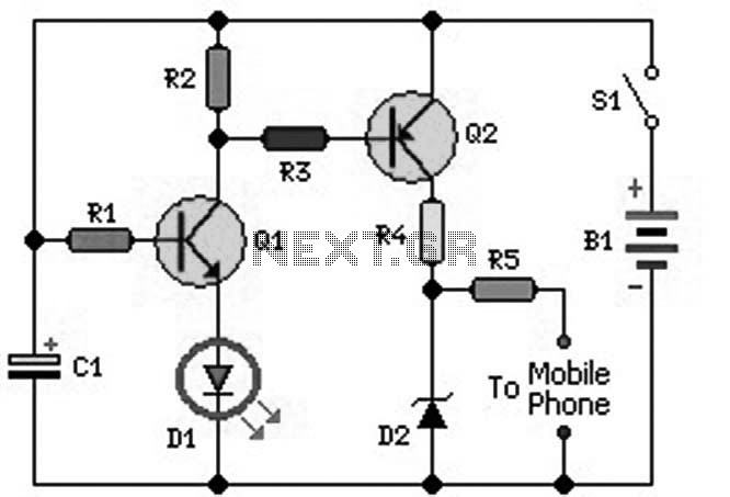
The operation begins when the user activates switch S1, which allows current to flow through the circuit. The activation of S1 causes transistor Q1 to enter its conductive state. This transistor functions as a switch that controls the flow of current to the rest of the circuit. The illumination of the green LED indicates that the circuit is operational and that charging is taking place.
Transistor Q2 is also engaged when Q1 conducts, as it receives a negative voltage at its base. This action ensures that both transistors work in tandem to facilitate the charging process. The charging current is directed from the collector of Q1 to the output terminals, where it can be connected to the mobile device.
To regulate the output voltage and ensure safe charging, a Zener diode (D2) is included in the circuit. This diode is critical in limiting the output voltage to a safe level of 4.7 volts, which is appropriate for charging most mobile phone batteries without risk of damage.
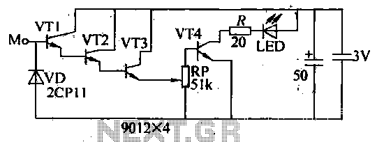
For charging applications requiring different current levels, the circuit incorporates a variable resistor (R4). By adjusting R4, users can switch between slow charging at a current of 20 mA and fast charging at a current of 80 mA by reducing the resistance to 47 ohms. This flexibility allows the charger to accommodate various devices and charging needs.
Output points are provided for connecting the charger to the mobile phone. It is imperative that suitable pins are used for this connection, and that they are connected with the correct polarity to avoid damaging the mobile device. This mobile charger design exemplifies a practical solution for charging devices in environments lacking standard AC power sources.An ideal Mobile charger using 1. 5 volt pen cells to charge mobile phone while traveling. It can replenish cell phone battery three or four times in places where AC power is not available. Most of the Mobile phone batteries are rated at 3. 6 V/500 mA. A single pen torch cell can provide 1. 5 volts and 1. 5 Amps current. So if four pen cells ar e connected serially, it will form a battery pack with 6 volt and 1. 5 Amps current. When power is applied to the circuit through S1, transistor Q1 conducts and Green LED lights. When Q1 conducts Q2 also conducts since its base becomes negative. Charging current flows from the collector of Q1. To reduce the charging voltage to 4. 7 volts, Zener diode D2 is used. The output gives 20 mA current for slow charging. If more current is required for fast charging, reduce the value of R4 to 47 ohms so that 80 mA current will be available. Output points are used to connect the charger with the mobile phone. Use suitable pins for this and connect with correct polarity. The circuit comes from here. 🔗 External reference
Related Circuits
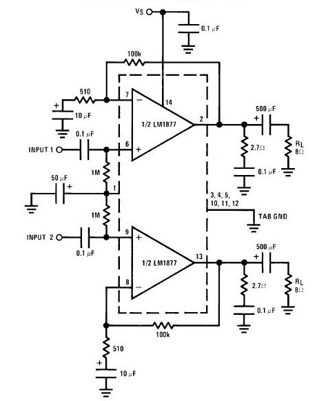
The LA4440 is a dual-channel audio power amplifier integrated circuit (IC) designed for stereo and bridge amplifier applications. In dual mode, it provides significant audio amplification for various audio systems. The LA4440 audio power amplifier is engineered to deliver high-quality...
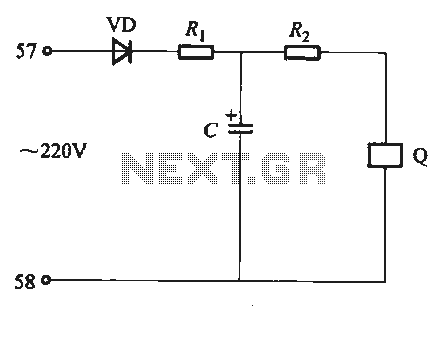
Undervoltage release operates over an extended period. When the power supply voltage drops within the operating voltage range, it triggers the release mechanism, resulting in the rotation of the tripping axle and the disconnection of the circuit breaker. There...
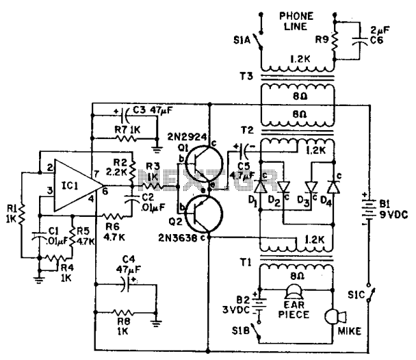
IC-1 and the associated circuitry form a stable audio tone generator that feeds a buffer amplifier, Q1 and Q2. The tone output is taken from the emitters of the transistor pair to supply a carrier voltage for a balanced...
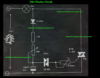
This circuit operates with 230V and can be used to decorate parties. It features a DIAC ER 900 and a TRIAC BTW 11-400. The circuit utilizes a DIAC (Diode for Alternating Current) and a TRIAC (Triode for Alternating Current) to...
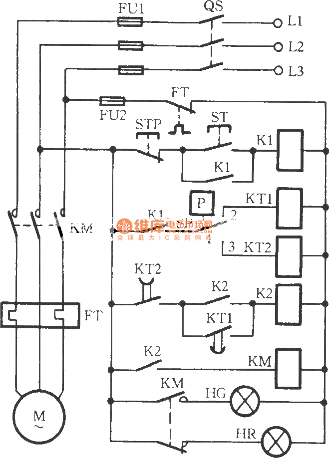
The circuit utilizes two time relays, KT1 and KT2, which are connected in series with the contacts of an electric contact pressure gauge (SP). This configuration helps to mitigate issues such as tremors or sparking that may occur due...
The internal disconnection circuit for a blanket operates on the principle of induction. It includes a wire approximately 2 cm in length that senses the proximity of a charged mains power source. When the sensing wire is close to...
Warning: include(partials/cookie-banner.php): Failed to open stream: Permission denied in /var/www/html/nextgr/view-circuit.php on line 713
Warning: include(): Failed opening 'partials/cookie-banner.php' for inclusion (include_path='.:/usr/share/php') in /var/www/html/nextgr/view-circuit.php on line 713