
LM258 LM258 Flex Sensor Circuit

The circuit described incorporates an accelerometer and Hall effect sensors to facilitate the control and operation of a robotic snake arm. The accelerometer serves as a motion sensor that detects changes in orientation and movement, allowing for precise control of the snake arm's position and movement dynamics. It can provide data regarding tilt and acceleration, which can be processed to determine the desired mode of operation for the arm.
The Hall effect sensors are strategically placed to detect magnetic fields, which can be used to determine the position of the arm segments or to enable specific operational modes based on the proximity of magnetic objects or components. These sensors can trigger different functionalities, such as switching between modes for movement, grasping, or other tasks.
The integration of these components into a cohesive circuit requires careful consideration of the signal processing and control logic. The accelerometer output can be interfaced with a microcontroller, which interprets the data to adjust the arm's movements accordingly. The Hall effect sensors can also be connected to the same microcontroller, allowing for simultaneous processing of inputs to ensure seamless operation.
Power supply considerations must also be addressed, ensuring that both the accelerometer and Hall effect sensors receive adequate voltage and current for optimal performance. Additionally, protective components such as resistors and capacitors may be included to filter noise and stabilize the circuit.
Overall, this configuration provides a versatile platform for controlling a snake arm robot, enabling it to operate in various modes based on real-time feedback from the accelerometer and Hall effect sensors.used to select modes of operation, the accelometer is used to generally move the snakearm while the hall effect sensors are designed to enable .. 🔗 External reference
Related Circuits

This system is compatible with 4-, 6-, or 8-cylinder automobiles. The timebase generated by IC5 functions as an oscillator that drives counter IC6, which divides the frequency by 6, 4, or 3 for 4-, 6-, or 8-cylinder engines, respectively....
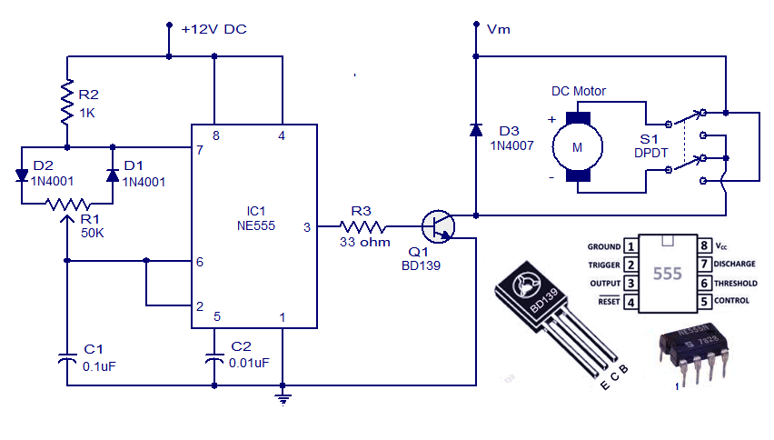
This weblog discusses electronic circuit schematics, PCB design, DIY kits, and electronic project diagrams. A simple DC motor controller circuit utilizing the NE555 timer is presented. Several DC motor speed control circuits are explored, with this being the first...

Have you already set up a Christmas tree in your house and decorated it with traditional lights? Build a couple of these LED lights to enhance the Christmas atmosphere. The project involves creating LED lights that can be used to...

The circuitry of the Regency exhibits several unique characteristics. Notable features include the self-oscillating mixer stage, the base bias voltage of the second IF stage derived from the AF power stage, an unusual IF frequency of 262 kHz, and...

This audio processor circuit utilizes the SSM2045 integrated circuit (IC), specifically designed for electronic music applications, alongside the 741 operational amplifier (op-amp) IC. The audio processor circuit is centered around the SSM2045, which is renowned for its ability to provide...
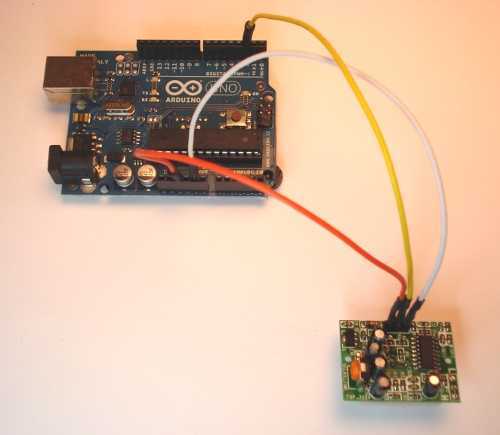
Give your Arduino board a motion sense around it! Use any Arduino board: Uno, Mega, Duemilanove etc. To implement motion sensing capabilities with an Arduino board, a typical circuit would involve the integration of a passive infrared (PIR) sensor, which...