
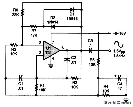
A variety of low-frequency waveform generator 741 circuit

The circuit operates by leveraging the properties of operational amplifiers configured in an integrator and comparator arrangement. The integrator stage converts input voltage into a ramp signal, which is then processed by the comparator to generate the desired output waveforms. The hysteresis in the comparator stage enhances stability by preventing rapid toggling between states, effectively filtering out noise that could lead to undesired waveform distortion.
In the triangle wave generation process, the integrator continuously ramps the voltage until it reaches the comparator's threshold. At this point, the comparator output toggles, causing the integrator to reverse its ramp direction. This behavior creates a linear increase and decrease in voltage, characteristic of triangle waves. The square wave is derived from the comparator output, which switches states at the same points that the triangle wave reaches its peak and trough.
In scenarios where a diode is incorporated into the output of the comparator, the circuit can produce sawtooth and pulse waveforms. The diode clamps the negative output, which modifies the waveform characteristics, resulting in a sharper transition between high and low states. The frequency of the output waveforms remains dependent on the time constant established by the resistor-capacitor (RC) network in the integrator stage, as well as the voltage division set by the resistors R1 and R2.
The operational amplifier's conversion rate is an important parameter, as it dictates the maximum frequency at which the circuit can reliably operate. With a limit of 5 kHz, the design is suitable for applications requiring low-frequency waveform generation, such as signal processing, waveform synthesis, and modulation tasks in various electronic systems. Overall, this circuit provides a versatile solution for generating essential waveforms in a compact and efficient manner. As shown in FIG variety of low-frequency waveform generating circuit. The circuit can simultaneously output two waveforms that triangle and square waves. Circuit, a first integ rator stage has a standard; a second gain stage inverter is 1; for the third stage of a comparator with hysteresis. In the third stage without diode, the circuit output is positive, the output of the integrator is negative syncline wave after wave inverted into a positive slant to the comparator.
When the ramp rate reached comparator threshold level Vo R1/(R1 + R2), the output is negative, then the integrator output is positive ramp; when the amplitude reaches a threshold level, and the circuit changes state, Thus, the first stage output triangle wave, square wave output of the third stage, the phase difference between them 180o. If the third-stage output plus one diode, since the clamping action of the diodes, the negative output of the comparator is -0.7V, then the circuit output sawtooth and pulse waves.
Whether plus access diode, the output frequency is determined by the time constant of the integrator, and a comparator supply voltage dividing ratio, its limit depends on the conversion rate of the operational amplifier. Limit frequency of the circuit is 5kHz.
Related Circuits
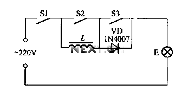
A portable four dimmer switch circuit is illustrated in Figure 8, featuring a four-speed brightness adjustment. When switches S1, S2, and S3 are all closed, the lamp operates at its brightest setting. When S1 and S2 are closed while...
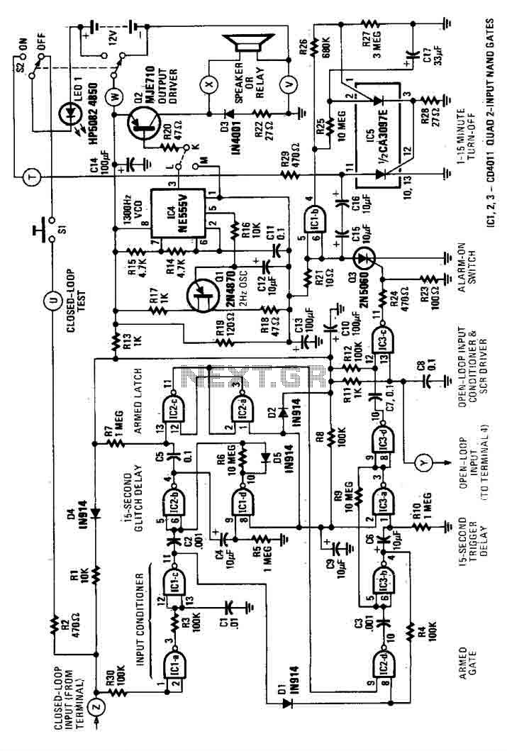
This house alarm circuit features both open and closed loop sensors and includes a self-shutdown function. The delay after triggering can be adjusted between 1 minute and 12 minutes, while the delay before triggering is set at 13 seconds....
This is a dry cell battery charger circuit designed to charge batteries over a period of approximately 12 hours. When powered by a 9-volt supply, the circuit is configured to accommodate AA-sized batteries. If C or D-sized batteries are...
This page is browser-friendly. To enhance readability, adjust your browser window to be narrower than the full screen. The page consists of two parts: the first part features a basic program demonstrating the RFID reader's functionality, while the second...
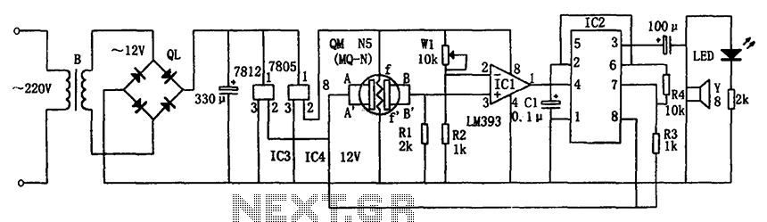
The circuit consists of a buck rectifier and voltage regulator, a gas sensor, a comparator circuit, and an alarm sound circuit. The buck regulator circuit includes a transformer, a bridge rectifier, and components such as QL, IC3 (7812), and...
A 741 operational amplifier is configured within a Wien-bridge audio sine-wave oscillator circuit. The components C1, C2, R1, and R2 are responsible for determining the operating frequency of the circuit. By utilizing NPO capacitors and metal-film resistors, the oscillator...