
555 double coil metal detectors

The double coil metal detector circuit operates based on the principle of electromagnetic induction, utilizing two coils to create a magnetic field. The transmitter coil generates an alternating magnetic field, which interacts with metallic objects within its vicinity. When a metal object enters the magnetic field, it induces eddy currents in the object, which in turn generate their own magnetic field. The receiver coil detects changes in the magnetic field caused by the presence of the metal object.
The multivibrator circuit (IC1) is configured to produce a square wave output, which is essential for driving the transmitter coil. The frequency of oscillation is dependent on the resistor and capacitor values in the circuit, allowing for adjustments to the sensitivity of the detector. The output pulse from the multivibrator triggers the timer (IC2), which controls the timing of the signal processing.
The differential amplifier (IC5) is crucial for amplifying the weak signals received from the coils. It enhances the detection capability of the circuit by increasing the signal-to-noise ratio, allowing for more reliable detection of metallic objects. The subsequent sense amplifier (IC6) further processes the amplified signal, preparing it for output to the timing circuit.
The timing circuit is responsible for generating precise delays, enabling the circuit to filter out false signals and respond only to significant changes in the detected signal. The two monostable circuits (IC3 and IC4) work in tandem to ensure that the output is stable and reliable.
The sound generator circuit adds a user-friendly interface to the metal detector. By producing an audible signal when metal is detected, it provides immediate feedback to the user, indicating the presence of metal without the need for visual indicators. The use of a 555 timer in the sound generator allows for easy adjustments to the tone and volume of the sound produced, enhancing the overall user experience.
In summary, this double coil metal detector circuit integrates various components to achieve efficient metal detection through electromagnetic principles, offering a practical solution for users in various applications, from treasure hunting to security. As shown in the following figure is double coil metal detector circuit. The probe by the probe, a transmitter, a receiver, a timer and sound transmitters and other components. Transmitter circuit shown in (b), by the multivibrator (IC1, R1, R2, C2), single stabilizer (IC2, R4, C4) composition, and the timer IC2 by multivibrator IC1 output pulse trigger. Oscillation frequency of f 1.44/(R1 + 2R2) C2, the corresponding icon parameter is about 100Hz. Timer in time td l.1R4C4, icon parameter corresponding to approximately 165 mu s. In the timing, (high) signal from the output enable pin IC2 BG1, BG2 saturated conduction. Receiving circuit shown in (c), mainly by the differential amplifier and the detector amplifier. Tibetan differential amplifier IC5 ( mu A709CP) the sensor signal diagram (b) of the coil differential amplification, the amplified signal during the open gates of a timing circuit through BG3, to the sense amplifier IC6.
A timing circuit shown in Figure (d) shown by the two monostable delay circuit IC3, R10, C7 and IC4, R12, C9 composition than, IC3 and IC4 by the output control. Wherein the delay time of the former is td l.1R12C9, icon parameter corresponding to about 36 mu s; the latter hope to delay time td2 1.1R10C7, icon parameter corresponding to about 50 mu s, the output signal supplied to receiver BG3, as open gates.
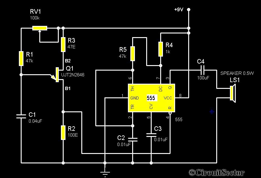
Sound generator as shown in (e), the core is composed of 555 (IC9), BG4, R26, R27, C17 and other multivibrator composed. When the metal-free sensor signal from the signal output enable pin IC6 BG4 off multivibrator does not work, corresponding speaker does not sound.
When metal sensing signal, and gradually close to the search coil metal body, the sensor signal becomes large, BG4 conduction situation changed for the better, so that the oscillation frequency IC9 gradually increased, when close to the metal body, high output by the IC9 oscillation frequency signal drives the speaker issued a high-frequency sound, it indicates there is a metal object.
Related Circuits
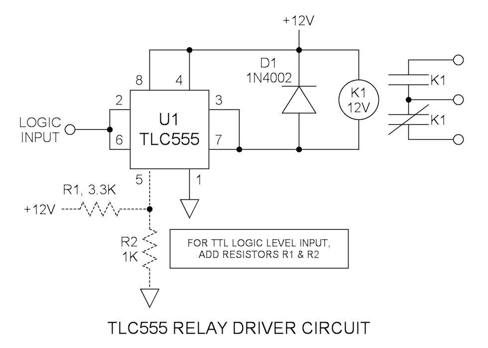
Many integrated circuits possess undocumented features or capabilities. The TLC555 output (pin 3) can sink a load of 100mA down to 1.28V. The open-drain transistor reset (pin 7) can also sink 100mA to 1V. Connecting both lines is permissible...

This coil gun design utilizes arbitrary on/off times that are calculated based on the basic equations of motion, rather than chosen randomly. The coils do not activate at uniform intervals; the first coil remains energized for the longest duration...
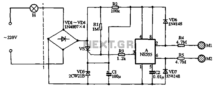
The circuit illustrated in the figure features a dashed line on the left, representing a standard lighting circuit, while the right side is responsible for the dual functionality of touch activation using the NE555 timer. Components VD1 through VD4...
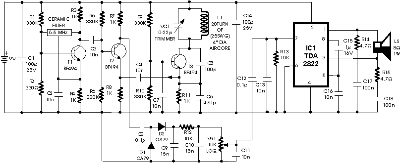
The circuit described is a metal detector. The operation of the circuit is based on the superheterodyne principle, which is commonly used in superheterodyne receivers. The circuit utilizes two RF oscillators, both fixed at a frequency of 5.5 MHz....
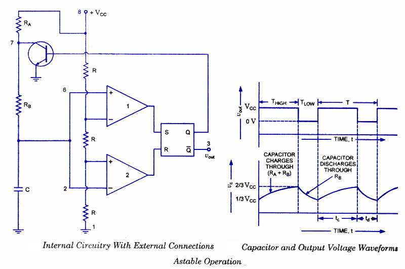
An astable multivibrator, often referred to as a free-running multivibrator, is a rectangular-wave generating circuit. Unlike the monostable multivibrator, this circuit does not require any external trigger to change the state of the output, hence the term free-running. Before...
The circuit diagram illustrates a timer 555-based rain sound generator. It requires a 9V DC power supply, which can be provided by a 9V battery. The circuit utilizes a 0.5W, 8-ohm speaker to produce sound. When powered by a...