
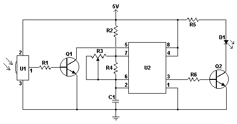
A circuit diagram of a danger zone warning device

The described circuit effectively integrates various components to create a comprehensive danger zone warning system. The regulator circuit ensures stable voltage levels for the various integrated circuits, while the pyroelectric infrared detection module provides real-time monitoring of the detection area. When motion is detected, the system activates both audio warnings and visual alerts through the flashing indicators, enhancing situational awareness. The electronic switch allows for seamless integration of different circuit functions, ensuring that the system operates efficiently. The low-frequency oscillator adds an additional layer of alert by providing a rhythmic visual signal, which can be critical in attracting attention. The careful selection of components ensures reliability and performance, making this circuit suitable for various applications where safety and alertness are paramount. Circuit works The danger zone warning circuit from the regulator circuit, the pyroelectric infrared detection trigger circuit, electronic switching circuit, voice circuits, aud io power amplifier, low frequency oscillator and a flash drive circuit and other components, as shown in FIG. Regulator circuit consists of three terminal regulator integrated circuit IC2, resistor R3, zener diode VS and filter capacitor C1, C2 components.
Pyroelectric infrared detection circuit is triggered by a pyroelectric infrared detection module IC1, transistor V1, V2, resistors R1, R2 and potentiometer RP. Electronic switching circuit from the electronic switch IC IC5, resistors R9, R10 and capacitor C8 composition.
Audio power amplifier circuit from the power amplifier integrated circuit IC4, resistors R6 ~ R8, capacitor C4 ~ C7 and speaker BL composition. Low-frequency oscillator circuit by the time-base integrated circuit IC6, resistors R11, R12 and capacitor C9, C10 and other components.
Flash drive circuit by the transistor V3, resistor R13 ~ R15, field effect transistor VF1, VF2 and indicator HL1, HL2 composition. + 12V supply voltage direct way IC4, IC5 and V2; another path IC2 regulator to + 5V, supply IC1; there all the way through R3 limiting, VS regulator generates + 3V voltage supply IC3.
IC1 internally by high sensitivity infrared sensor, high-gain low-noise amplifier, automatic temperature compensation circuit, signal comparison discriminating circuit, delay circuit, high and low drive circuit. In the static (that no one enters the detection area), 1 foot IC1 output low, the output of 2 feet high, the transistor V1 and V2 are closed, Wu made the circuit does not work, BL does not sound speakers; electronic switching circuit is in the OFF off state, the low-frequency oscillator without the power supply instead of working, HL1 and HL2 does not emit light.
When someone enters the detection zone IC1, IC1 pin 1 from low to high, so that V1 conduction, IC3 triggered by the work, its output voice signal (O/P side) output by IC4 after amplification, the driving speaker BL hazard, do not close language warning sound. At the same time, IC1 2 feet from the high to low, so that V2 conduction, IC5 internal electronic switch is turned on, the power supply to obtain low-frequency oscillator oscillates work, 3 feet from IC6 output operating frequency 2Hz low frequency pulse signal, so HL1 and HL2 flash alternately (when the signal is positive pulse, VFI is turned on, HL1 is lit: when the signal is negative pulse, V3 conduction and VF2, VF1 off, H12 is lit) issuing reminders flash signal.
Component selection R1 ~ R7, R9 ~ R15 choose 1/4W carbon film resistors or metal film resistors; R8 selection 1/2W metal film resistors. RP use of small potentiometer or variable resistor. C1, C2, C4 ~ C6, C8, and C9 are selected voltage is 10V or more small electrolytic capacitors; C3, C7 and C10 use polyester capacitors, monolithic capacitors or CBB capacitor.
V1 selects 59014 or 3DG9014 silicon NPN transistor; V2 and V3 selection 59012 or 3DG9012 silicon PNP transistors. VF1 and VF2 selection 2SK1530 or IRF1390 field effect transistor. IC1 selects HN911L type pyroelectric infrared detection module (detection distance of 10m, the azimuth angle of 100 ); IC2 selected type LM7805 or 78L05 type three-terminal integrated voltage regulator; IC3 selected within the reservoir dangerous, do not close.
language IC; IC4 type selection TDA2002 audio power amplifier integrated circuits; IC5 selected TWH8778 electronic switch IC; IC6 NE555 type used when the base integrated circuit. BL choose 8 (or 4 ), 3 ~ 5W electric speaker. HL1 and HL2 small selection of vehicles with 12V bulb.
Related Circuits
This infrared (IR) remote extender enhances the range of most basic IR remotes operating at a 40KHz modulation frequency significantly. When in operation, the remote is aimed at the detector on the circuit, and a button is pressed. The...
This is a straightforward high-quality PLL FM transmitter with a typical output power of 5 W and a no-tune design. It features RDS/SCA input and audio/MPX input with optional pre-emphasis and can operate with or without a stereo encoder....

This design circuit is for a simple 27MHz transmitter that produces a carrier signal. The circuit generates an unmodulated 27MHz signal, which can be received by a compatible receiver. The transmitter operates as a basic crystal oscillator, with the...
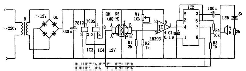
The circuit consists of a buck rectifier and voltage regulator, a gas sensor, a comparator circuit, and an alarm sound circuit. The buck regulator circuit includes a transformer, a bridge rectifier, and components such as QL, IC3 (7812), and...
It is essentially an all-pass filter with two additional components: a capacitor and a resistor, which produces percussion sounds. A schematic of the unmodified all-pass filter circuit, a waveform captured via Audacity, and a short audio sample featuring a...
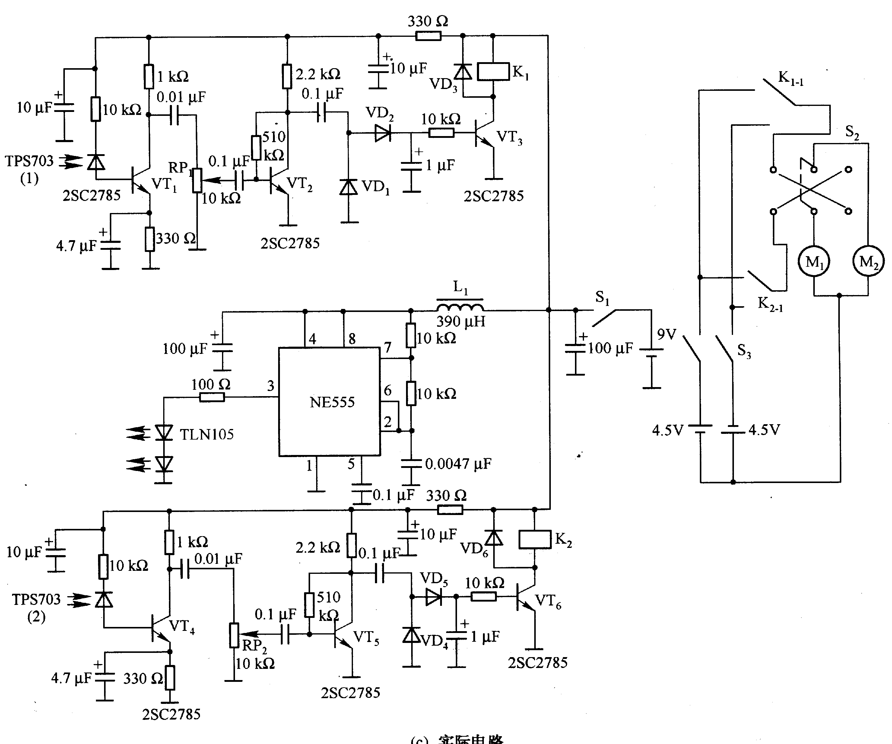
Figure 2-33 (a) illustrates the schematic diagram of a robot approaching an object. When no objects are detected in front of the robot, it moves forward in a straight line. If an object is detected on the left or...