
ir remote extender circuit
The IR remote extender circuit utilizes a Sharp IR detector to receive signals from a standard IR remote control. The received 40KHz modulated signal is processed and converted into a series of electrical pulses. These pulses are fed into a CMOS TLC555 timer configured in monostable mode, which generates output pulses at the same frequency as the input signal. The output from the 555 timer is then used to drive an IR LED, which emits IR light that can be detected by the intended device, such as a television or audio system.
To ensure reliable operation, the circuit design incorporates a few key components: the Sharp IR detector, the TLC555 timer, and the IR LED. The use of shielded cable for extending the output LED is essential to minimize interference and maintain signal integrity over longer distances. The calibration process is crucial, as it ensures that the circuit operates at the correct frequency, allowing for optimal performance of the IR remote extender.
The configuration of the circuit should include appropriate power supply decoupling to prevent voltage fluctuations from affecting the performance of the timer and the IR detector. Additionally, the design may include filtering capacitors to smooth out any noise in the power supply line. The selection of the IR LED must also consider its wavelength and intensity to ensure compatibility with the devices being controlled.
In summary, this IR remote extender circuit provides a practical solution for extending the operational range of standard IR remotes in environments where direct line-of-sight is obstructed. Proper calibration and component selection are essential for achieving the desired performance and reliability.This IR remote extender can increase the range of most simple IR remotes (those operating on a 40KHz modulation) a significant distance. In use, the remote is pointed toward the detector on the circuit, and a button is pressed. The Sharp IR detector then decodes the 40KHz modulated signal into a series of pulses, which trigger a 555 timer.
The 555 outputs pulses which are re-modulated and used to drive an IR LED. The circuit is excellent for use in a large room like a presentation hall where a typical IR remote is a bit weak. By extending the wires to the output LED (using shielded cable) you can control a device where line of sight isn`t available (such as a wall full of TVs in another room).
Only the CMOS TLC555 timer can be used in this circuit. The original NE555 cannot operate reliably at 40KHz. Acceptable substitutions are shown in the parts list. To calibrate the circuit, use a frequency counter. Connect it in parallel with D1 and then ground the base of Q1. Adjust R3 for 40KHz on the counter. If a counter is not available, you will just have to point a remote at the circuit, press a button, and then adjust R3 until it works. This can take a few tries as not all remotes transmit continuously. 🔗 External reference
Related Circuits
Even if the circuit is simple, it complies with all conditions regarding distortion and frequency response. The input resistance is 250K ohms, and it can drive loads ranging from 100 ohms to 2K ohms. The described circuit is a fundamental...
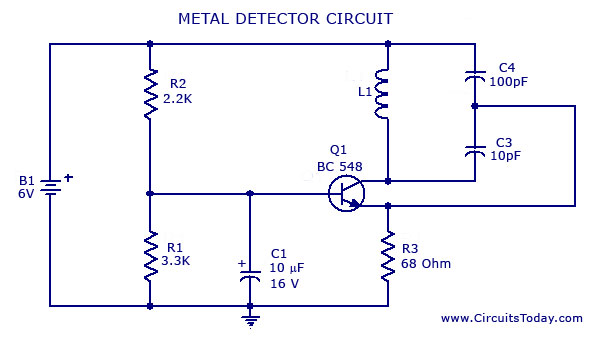
A simple metal detector circuit diagram and schematic using a single transistor and a radio. This metal detector/sensor project is easy to make and is an application of a Colpitts oscillator. The metal detector circuit utilizes a single transistor in...
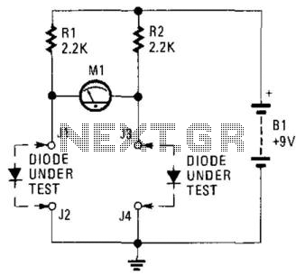
This circuit can be utilized to match diodes for applications where balance is essential, such as in a balanced modulator. The diode matching circuit will display the forward voltage drop of the two diodes in millivolts. The diode matching circuit...

A biaxial magnetic field sensor application circuit is illustrated in the figure. This circuit utilizes a biaxial magnetic sensor HMC1002 along with two AMP04 operational amplifiers (A1, A2) to measure the magnetic field in both the X-axis and Y-axis...

Construct a temperature controller circuit using the 555 integrated circuit (IC) in combination with a thermistor resistor divider. The benefit of this design is that it does not require a well-regulated power supply. The resistor divider network comprises an...
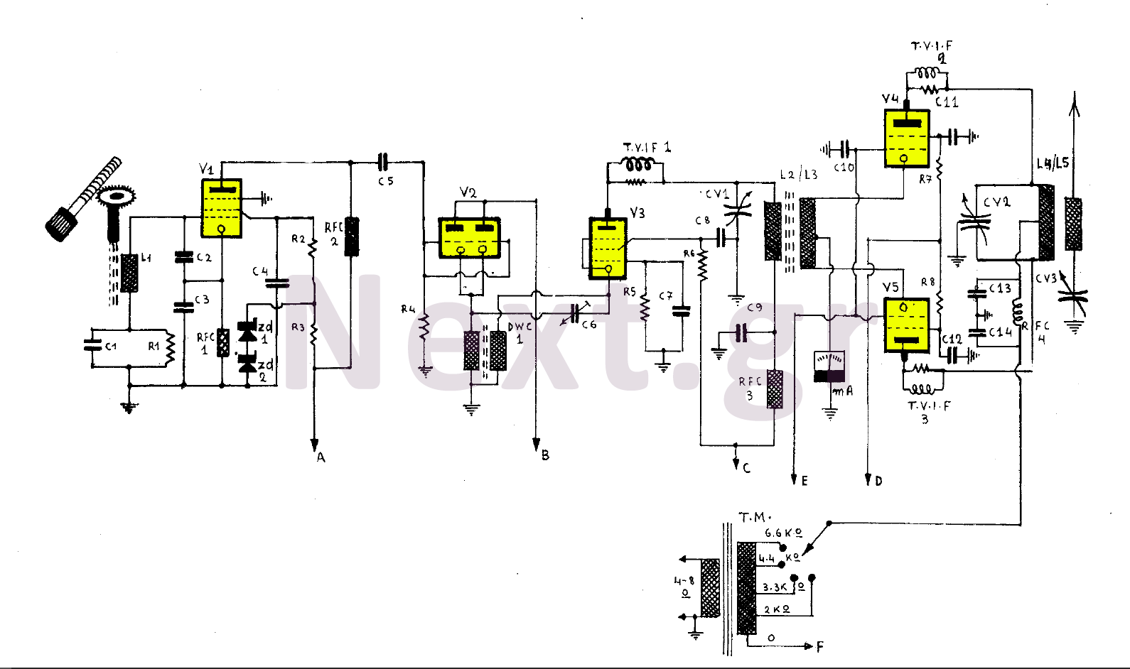
This 255W transmitter operates using coils designed for both medium and short waves. The antenna power is set at 255W and includes four operational states. The first state utilizes an EF80 tube functioning as a Colpitts Clapp oscillator. Frequency...
Warning: include(partials/cookie-banner.php): Failed to open stream: Permission denied in /var/www/html/nextgr/view-circuit.php on line 713
Warning: include(): Failed opening 'partials/cookie-banner.php' for inclusion (include_path='.:/usr/share/php') in /var/www/html/nextgr/view-circuit.php on line 713