
ND838 application circuit

The described figures depict various output configurations capable of interfacing with different electronic components. Each output is designed to provide the necessary drive capability to control various devices, including transistors which are essential for amplification and switching applications, thyristors for high-power control, and relays for electrically operated switches. Additionally, the outputs can drive CMOS and TTL circuits, which are fundamental in digital electronics for logic operations and signal processing.
Transistors, such as BJTs and MOSFETs, require specific voltage and current levels to operate effectively. The outputs illustrated in the figures are tailored to meet these requirements, ensuring reliable operation within their respective applications. Thyristors, known for their ability to handle high voltages and currents, also benefit from such direct drive capabilities, allowing for efficient control in power electronics.
Relays, which serve as electromechanical switches, can be directly driven by these outputs, facilitating the control of high-power loads while isolating the control circuit from the load circuit. The compatibility with CMOS and TTL circuits indicates that the outputs can operate in both low-power and high-speed environments, making them versatile for various digital applications.
In summary, the outputs in Figures (A), (B), (C), and (D) are designed to interface directly with a range of electronic components, providing essential drive capabilities for transistors, thyristors, relays, CMOS, and TTL circuits. This versatility makes them suitable for a wide array of electronic applications, from simple switching to complex logic operations.FIG. (A), (b), (c), (d), respectively, which output can directly drive transistor, thyristor, relay, COMS circuits, TTL circuits.
Related Circuits
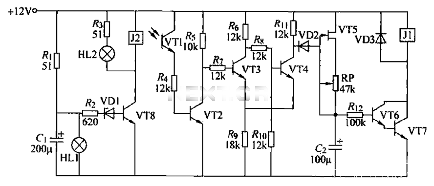
A blocking material monitoring circuit is presented. When the optical path is obstructed by the material, the phototransistor VT1 turns off, which subsequently turns off transistors VT2, VT3, and VT4. This arrangement is coupled to a flip-flop configuration. When...
Probably the easiest way of doing automatic switch off is with relay logic. In the diagram, the box marked RL1 is the coil, the 2 in the coil box tells you there are two sets of contacts somewhere on...
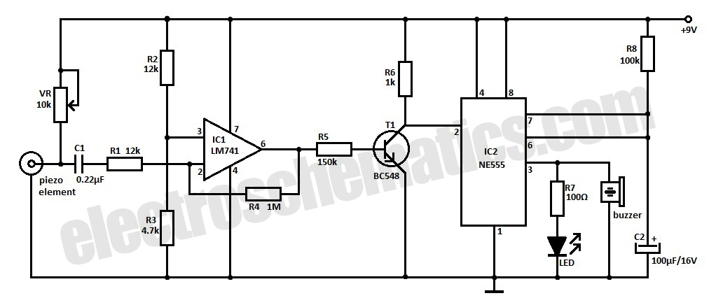
This is an ultra-sensitive earthquake detector circuit capable of sensing seismic vibrations. It can be utilized to detect vibrations in the Earth. The ultra-sensitive earthquake detector circuit is designed to respond to minute seismic vibrations, making it an essential tool...
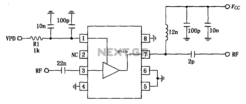
The circuit is based on an 880 MHz RF2347 low noise amplifier application. The radio frequency (RF) signal enters through input pin 3, and after amplification, the output is available at pin 7. The amplifier is directly coupled to...
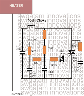
Controlling heaters rated up to 1500 watts requires stringent specifications for the controlling unit to ensure safe and effective operation. The introduction of advanced snubber-less Triacs and Diacs has made it relatively easier to implement heater controllers at high...
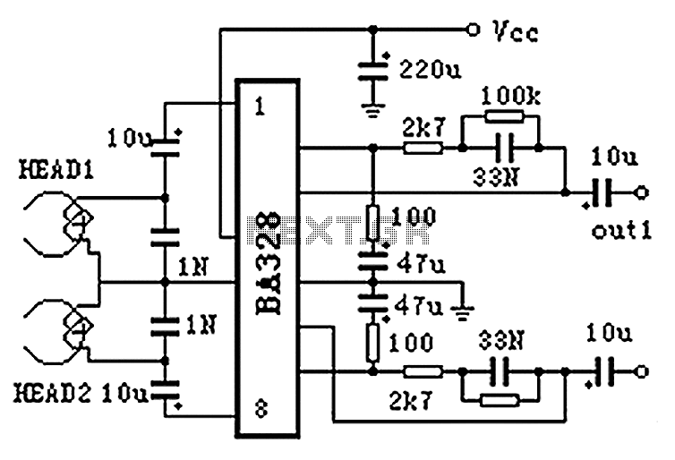
The BA328 is a dual preamplifier circuit designed with minimal external components, facilitating straightforward installation within a single 8-pin DIP package. The circuit features a wide operating voltage range, low noise levels, and high open-loop gain, ensuring good balance...