
How to Make a 25 Amp 1500 watts Heater Controller Circuit
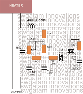
The heater control circuit operates by utilizing a Triac and Diac in conjunction with a resistive-capacitive (RC) network. The RC network is crucial for timing the firing of the Diac, which in turn triggers the Triac. The Diac remains off until the voltage across it exceeds its breakover voltage, which is determined by the values of the resistors and capacitors in the network. When the Diac fires, it allows current to flow through the Triac, effectively turning on the heater.
The potentiometer serves as a variable resistor that adjusts the charging time of the capacitor in the RC network. By increasing the resistance, the charging time of the capacitor is prolonged, which delays the firing of the Diac. This results in a shorter conduction time for the Triac during each AC cycle, thereby reducing the average power delivered to the heater. The relationship between the potentiometer setting and the heater output is linear; as the resistance decreases, the capacitor charges faster, resulting in more frequent triggering of the Triac and a corresponding increase in the average voltage supplied to the heater.
This method of phase control allows for precise temperature regulation of the heating element, making it suitable for applications where temperature control is critical. The circuit can be designed to handle high power levels while maintaining safety standards, ensuring that the components can withstand the thermal and electrical stresses associated with high-wattage operation. Proper heat sinking for the Triac is also essential to prevent overheating during operation.Controlling heaters rated as high as 1500 watt requires stringent specifications with the controlling unit for safe and effective implementation of the intended operations. With the advent of advanced snubber-less Triacs and Diacs makingheatercontrollers at massive watt levels has become relatively easier today.
The set up of the circuit is pretty standard as the the wiring is very similar to the ones which are normally employed in ordinary light dimmer switch circuits. The following network resistors and capacitors associated with the diac are chosen such that they allow the diac to fire only as long as the sine curve remains below a certain voltage level.
The above conduction of the triac only for a specifiedsectionof the input sine voltage curve, results in an output across the triac which has the AC chopped into smaller sections, making the overall RMS of the resultant drop to a lower value, depending upon the values of the relevant resistors and capacitors around the diac. The pot which is shown in the figure is used forcontrollingthe heaterelementwhich initiates the above explained procedure.
The greater the resistance, the longer it takes or the capacitor to charge and discharge whih in turn prolongs the firing of the diac/triac pair. This prolongation keeps the triac and the load switched OFF for a longer section of the AC sine curve which results correspondingly lower average voltage to the heater, and the heatertemperatureremains at the cooler side.
Conversely when the pot is adjusted toward toproducea lower resistance, the capacitor charge and discharge at a faster rate making the abovecyclerapid which in turn keeps the average switching period of the triac at the higher side, resulting a higher average voltage to the heater. The heater now generates more heat due to the increased averagevoltagedevelopedacross it via the triac.
🔗 External reference
Related Circuits
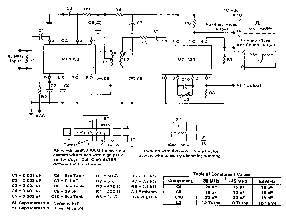
The circuit exhibits a typical voltage gain of 84 dB and an automatic gain control (AGC) range of 80 dB. It demonstrates minimal alterations in bandpass shape, generally less than 1 dB tilt for 60 dB compression. There are...
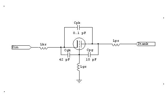
Grid-driven tetrodes such as the 6146, 807, or 4CX250 exhibit high power gain. High-gain systems require minimal feedback to remain stable, which necessitates neutralization. Additionally, these systems often need a grid loading resistor to stabilize or reduce gain. The...
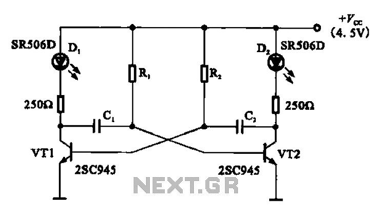
The multivibrator flashing light emitting diode (LED) display driver circuit can be utilized in toys, creating flashing effects in the eyes of animals or monsters. This circuit employs a multivibrator configuration, typically a 555 timer IC or a similar component,...

The 555 timer integrated circuit (IC) is an exceptionally versatile component utilized in various applications, including generating clock pulses, switch debouncing, and functioning as an output transducer. The standard 555 IC is packaged in an 8-pin configuration, available in...
The count switching circuit consists of an electronic switch and a pulse delay circuit for control. The count switching circuit is designed to manage the switching of signals in a controlled manner. The electronic switch serves as the primary component...
This circuit is a diagram of a mini amplifier. The amplifier circuit has a power output of 10 watts and is well-suited for car audio applications. It utilizes the TDA2009A integrated circuit as the power amplifier. To prevent excessive...