
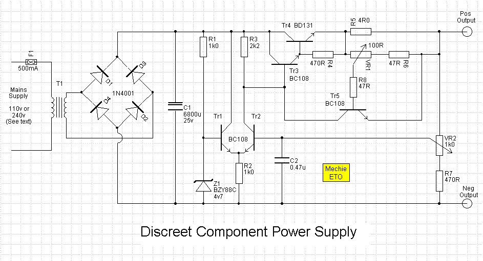
0-12V 2A power supply
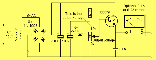
This project involves designing a power supply circuit that can operate either from a mains source using a 2155 or 2156 transformer or from a 16V AC plug pack. The choice between these two options is critical for ensuring safety and efficiency. The recommended plug pack is a 16V AC 1 amp model, which is double insulated, thereby enhancing safety during operation.
In terms of performance, while the 2 amp M 2156 transformer can supply a maximum of approximately 1.4 amps DC output, the 1.5 amp AC plug pack provides a similar rating, making it a viable alternative. The cost considerations also favor the plug pack, as it can be more economical than purchasing a transformer and power cord separately.
Heat management is a crucial aspect of this power supply design. A heatsink is necessary to dissipate heat generated by the power components, particularly the transistor. The heatsink must be appropriately sized, with a recommended trial size of approximately 4cm x 10cm. To ensure that the heatsink is adequately sized, a practical approach is to load the power supply to its maximum rating using high wattage resistors or car lamps. During this testing phase, monitoring the temperature at both the transistor and the heatsink is essential to assess thermal performance.
The heatsink should be mounted in direct contact with the transistor and the printed circuit board (PCB) to ensure efficient heat transfer. Proper thermal contact is vital; any inefficiency in this area could lead to overheating and potential damage to the transistor. Therefore, careful attention must be paid to the assembly and mounting of the heatsink to guarantee optimal thermal management in the power supply circuit.This project has two options. It can be a mains operated project, using a 2155 or 2156 transformer or it can be connected to a plug pack. We recommend it be connected to a 16v AC 1 amp plug pack as these are double insulated and provide complete safety for the constructor.
As we have mentioned in the introduction, the 2 amp transformer M 2156 will not provide much more than 1.4 amps DC output so the 1.5 amp AC plug pack has nearly the same rating. By the time you buy a M 2156 transformer and power cord, the total will be the same as the cost of the plug pack so it should be one of your considerations.
The heatsink is one of the most important components in a power supply. It must provide adequate heat dissipation to protect a heat-sensitive device, from being damaged. All power supplies dissipate heat. Some are more efficient than others but whenever voltage and current are present together, heat will need to be dissipated. The way to select the correct-size heatsink is to build the project and fit a heat sink about 4cm x 10cm as a trial experiment.
Next you need some high wattage resistors or car lamps to load the power supply to its maximum rating (this will depend on the transformer you use). Place one finger on the transistor and another on the heatsink, about 2cm from the transistor, and monitor the temperature rise in both positions.
The heatsink in our project fits between the metal side of the transistor and PC board to get direct contact with the transistor. It is most important to get good thermal contact so that any heat generated in the transistor will be carried away by the heatsink.
🔗 External reference
Related Circuits
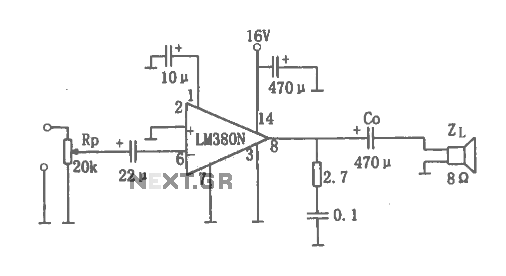
This document details a 2W audio power amplifier circuit that utilizes a 14-pin LM380 package as the amplification element. The input signal is managed by a volume control potentiometer (Rp) rated at 20k ohms, with a coupling capacitance of...
A real-size printout of the PCB is created to verify the dimensions of all components against it. If a component is too large or small to fit its PCB pads, adjustments to the PCB layout can be made, or...
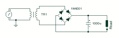
A basic full wave rectified power supply is shown below. The transformer is chosen according to the desired load. For example, if the load requires 12V at 1amp current, then a 12V, 1 amp rated transformer would do. However,...
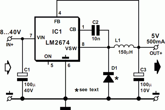
This 5-volt Switch Mode Power Supply circuit utilizes an integrated circuit (IC) from National Semiconductor, which specializes in the production and design of ICs for switch-mode power supply applications. The 5-volt Switch Mode Power Supply (SMPS) circuit is designed to...

This audio amplifier design utilizes TMOS Power FETs configured in a complementary common-source arrangement. The FETs are biased to cutoff and can rapidly turn on when a signal is applied. This design approach offers significant thermal stability in the...
An error amplifier is constructed using transistors Tr1 and Tr2, configured as a differential amplifier, commonly referred to as a long-tailed pair, with the collector leads being a notable feature. One input of this differential amplifier is sourced from...