
Unregulated Power Supply
The described full wave rectified power supply circuit employs a transformer, a rectifier, and filtering components to convert alternating current (AC) to direct current (DC). In this configuration, the transformer steps down the input AC voltage to a desired lower voltage level suitable for the load. For instance, a transformer rated at 12V and 1A is appropriate for a load requiring 12V at 1A. However, to ensure reliability and longevity of the power supply, it is prudent to select a transformer with a higher current rating, ideally 1.5A to 2A, to accommodate potential load variations and prevent overheating.
The rectification process in a full wave rectifier typically utilizes either a bridge rectifier configuration or a center-tapped transformer with two diodes. The bridge rectifier consists of four diodes arranged in a bridge configuration, allowing both halves of the AC waveform to contribute to the output DC voltage. This arrangement is beneficial as it maximizes the efficiency of the rectification process by utilizing the entire input waveform, resulting in a smoother DC output.
After rectification, a filtering stage is often implemented to reduce the ripple voltage present in the output. This is commonly achieved using capacitors, which store charge and release it to smooth out fluctuations in the output voltage. The capacitor value is determined based on the load current and the acceptable ripple voltage; larger capacitance values will yield lower ripple but may increase the physical size and cost of the power supply.
Finally, a voltage regulation stage may be included to maintain a stable output voltage under varying load conditions. This can be achieved through linear voltage regulators or switching regulators, depending on the application requirements, efficiency considerations, and thermal management.
Overall, careful selection of components and consideration for worst-case scenarios are essential in designing a robust full wave rectified power supply that meets the needs of the intended electronic application.A basic full wave rectified power supply is shown below. The transformer is chosen according to the desired load. For example, if the load requires 12V at 1amp current, then a 12V, 1 amp rated transformer would do. However, when designing power supplies or most electronic circuits, you should always plan for a worst case scenario. With this in mind, for a load current of 1 amp a wise choice would be a transformer with a secondary current rating of 1.5 amp or even 2 amps.
Allowing for a load of 50% higher than the needed value is a good rule of thumb. 🔗 External reference
Related Circuits
This simple circuit is designed to provide an output power of approximately 1 watt when connected to a 9-volt power supply. The key advantage of this circuit is its use of a dual Darlington configuration, which increases the input...
Simple and low cost. The optimal supply voltage is around 50V, but this amp works from 30 to 60V. The maximal input voltage is around 0.8 - 1V. As you can see, in this design the components have a...
This simple audio power amplifier was originally designed for a circuit board workshop, conducted by the OSU IEEE Student Group. At the workshop, 20 participants each constructed this amplifier, by etching and drilling the single sided circuit board, soldering...
The TDA2040 is a monolithic integrated circuit housed in a Pentawatt package, designed for use as an audio class AB amplifier. It typically delivers an output power of 22W (with a distortion factor of 0.5%) at a supply voltage...
This audio amplifier design utilizes two LM3886 chips per channel in a parallel configuration, based on the PA100 parallel amplifier detailed in National Semiconductor's application note AN1192. The amplifier can deliver approximately 50W into an 8-ohm speaker and 100W...
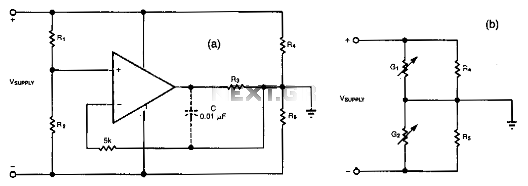
This simple circuit can convert a single supply voltage, such as a battery, into a bipolar supply. Sense resistors R1 and R2 establish relative magnitudes for the resulting positive and negative voltages. Their rail-to-rail value equals V_SUPPLY. Resistors R4...