
stabilised power supply current limiting
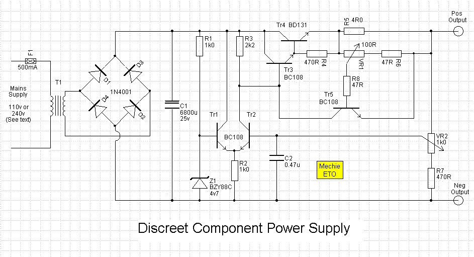
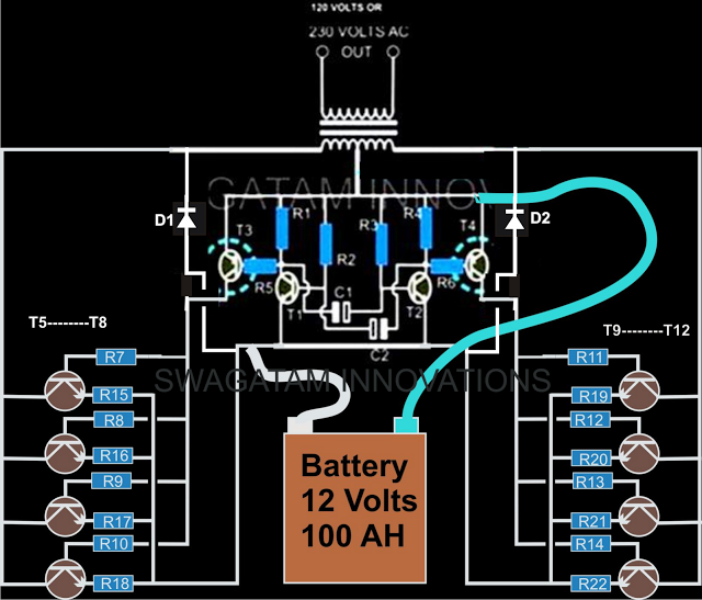
The described circuit employs a differential amplifier configuration for error detection and regulation, utilizing a zener diode for voltage stability. The differential amplifier's design, featuring Tr1 and Tr2, allows for precise comparisons between a stable reference voltage and a feedback voltage derived from the output, enabling effective regulation of the output voltage. The current sensing mechanism, facilitated by R5, provides an essential feedback loop to maintain output stability under varying load conditions.
The Darlington pair formed by Tr3 and Tr4 amplifies the current gain, ensuring that the output can handle higher currents without compromising voltage regulation. The emitter-follower configuration enhances the circuit's ability to drive loads while maintaining a stable output voltage. The inclusion of a current limiting feature via Tr5 protects the circuit from overcurrent conditions, enhancing reliability and preventing damage to components.
Thermal management is critical in this design, particularly for Tr4 and R5, which require adequate heat dissipation measures to function effectively under load conditions. The suggested use of a heatsink and proper resistor ratings ensures that the circuit operates within safe thermal limits. The implementation of a user-adjustable current scale on Vr1 allows for convenient operation and adaptability to various load requirements, making the circuit versatile for different applications.
In summary, this circuit design effectively combines error amplification, current regulation, and thermal management to create a robust power supply solution, suitable for a range of electronic applications.An error amplifier is formed from Tr1 and Tr2, wired as a differential amplifier (often called a long-tailed pair - look at those collector leads). One input of this diff. amp is taken from the zener diode which provides a stable 4. 7 volts, the other diff. amp input is a fraction of the output. Any difference between the two will cause the curren t through R3 to alter and so will alter the voltage across it and hence to the base of Tr3. Tr3 and Tr4 are connected as a darlington pair, this produces a very high gain to aid stability of regulation. This darlington pair can be visualised as a single transistor connected in an `emitter-follower` configuration, the emitter voltage will follow the base voltage (less the 1.
2v required to forward bias the two base-emitter junctions), but with a much greater current capacity. Current limiting is provided by Tr5 which will be forward biassed by a fraction of the voltage drop across the current sensing resistor, R5, set by Vr1.
As the current through R5 increases so does the voltage dropped across it, this begins to bias Tr5 on and in so doing causes Tr3/Tr4 to be deprived of base current and so reduces the output voltage. Tr4 needs a heatsink of at least 10 degrees C/Watt (10C / W) and R5 is expected to carry (1A * 4R) = 4 Watts, so it will need to be a 5W device or four 1R 1W devices in series, mount them on a peice of metal as they will get hot!
As there is no current measurement built in to the unit, a useable scale could be marked around the potentiometer Vr1`s knob such that a known current could be chosen in advance of connecting a load. To do this, connect an ammeter directly across the power supplie`s output - this will instantly overload the supply and cause the current limiting to operate.
Adjust Vr1 so that the ammeter displays 500mA and mark the knob`s position. Repeat the procedure for 600mA, etc. ## DON`T keep the supply shorted for too long as Tr4 and R5 will soon get hot! ## 🔗 External reference
Related Circuits
This power factor controller accepts voltages ranging from 90 to 268 Vac, which is why it is referred to as a power factor controller with universal input, as it accommodates the mains supply standards in nearly any country. The...
This circuit is a class AB stereo audio power amplifier designed by Quasar for high-fidelity applications using a TDA2005 module. It is straightforward to construct and requires a minimal number of external components. The module includes output current protection...
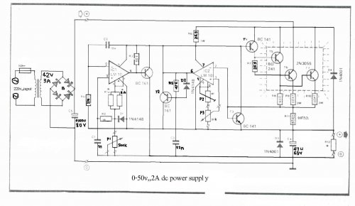
The LM10 integrated circuit (IC) is utilized due to its reference voltage feature, which is advantageous for DC power supply applications. By employing two LM10 ICs, different output voltages and current levels can be achieved. This circuit includes short-circuit...
This shows the overall circuit diagram of the power control unit. On the left, there is a main relay controlled by the key switch. The power control unit circuit diagram illustrates the fundamental components and their interconnections, providing a clear...
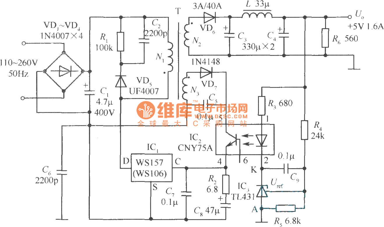
The +5V, 1.6A precision switching power supply circuit is depicted in the figure. This circuit utilizes a photoelectric coupler (CNY75A) and an adjustable precision parallel regulator (TIA31). R3 serves as the current limiting resistor, while R4 and R5 function...
The current design of a power inverter offers an efficiency of approximately 85% and a power output exceeding 200 watts. This document provides a complete circuit schematic and detailed building procedure for a home-built power inverter. While numerous articles...
Warning: include(partials/cookie-banner.php): Failed to open stream: Permission denied in /var/www/html/nextgr/view-circuit.php on line 713
Warning: include(): Failed opening 'partials/cookie-banner.php' for inclusion (include_path='.:/usr/share/php') in /var/www/html/nextgr/view-circuit.php on line 713