
0.1V to 50V Variable Power Supply
The variable power supply circuit is designed to provide an adjustable output voltage ranging from 0.1V to 50V, making it suitable for various electronic applications. The circuit incorporates an operational amplifier (op-amp) CA3130, which plays a critical role in voltage regulation by comparing the output voltage against a stable reference voltage.
The power supply's adjustable output is typically achieved through the use of a potentiometer or a variable resistor, which allows the user to set the desired voltage level. The circuit also includes a current limiting feature, which ensures that the output current does not exceed 0.6 amperes, protecting both the power supply and connected devices from potential damage due to overcurrent conditions.
In addition to the op-amp, the circuit may utilize a combination of voltage regulators and pass transistors to achieve the desired voltage range and current capacity. The design may also include filtering capacitors to reduce voltage ripple and improve output stability.
Protection components, such as diodes, may be implemented to prevent reverse polarity and overvoltage situations. Overall, this variable power supply circuit is a versatile tool for testing and powering various electronic components and systems, providing reliable performance across a wide range of operating conditions.0.1V to 50V Variable Power Supply Circuit Diagram. Features: the lowest current limit is 0.6 ampere, opamp CA3130 compares the reference voltage .. 🔗 External reference
Related Circuits
This is a very simple circuit utilizing a 555 timer IC to generate a square wave of frequency that can be adjusted by a potentiometer. With values given, the frequency can be adjusted from a few Hz to several...
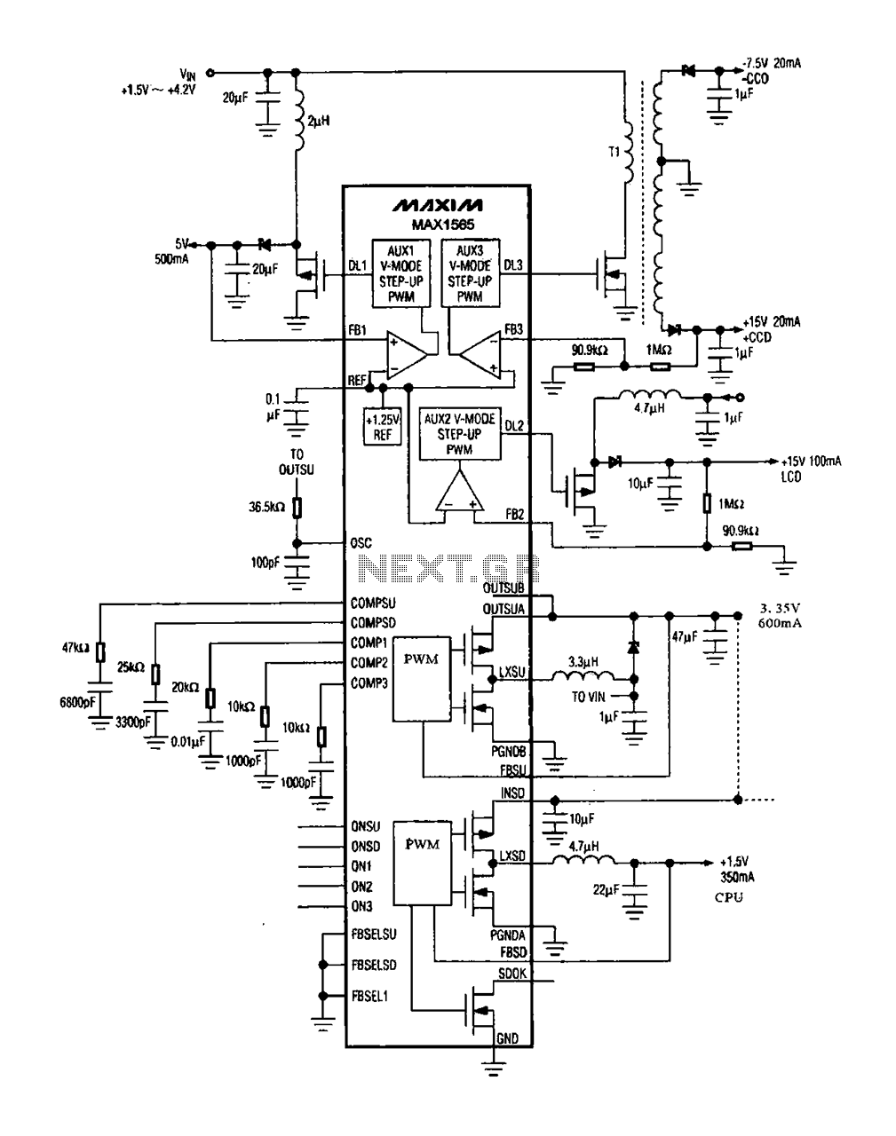
The digital camera power supply utilizes the MAX1565 chip, which features a five-channel power supply configuration. The chip generates various signal widths and control circuits tailored to meet the DC voltage and current requirements of the digital camera. The...
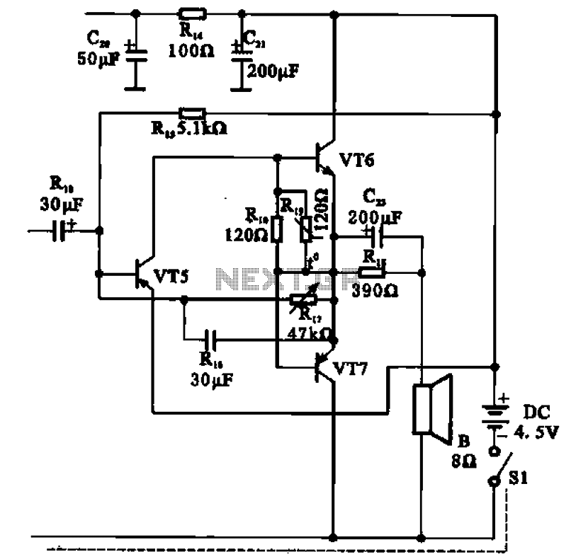
The transistor radio features a common output transformerless (OTL) power amplifier circuit. The VT5 component serves as the bias resistor for the driver stage. VT6 and VT7 form a complementary symmetry configuration, with VT6 being a germanium NPN transistor...
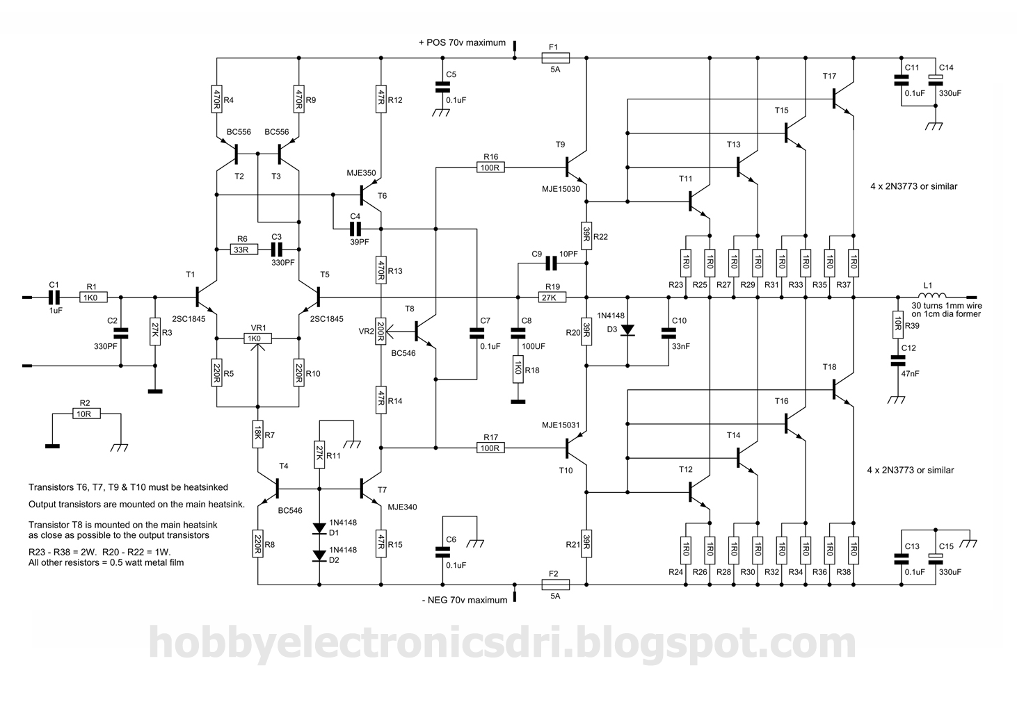
This amplifier was designed to utilize the otherwise unused TO3 power transistors that many hobbyists possess. With proper construction, the module can achieve high-quality performance and is rated for 300 watts into a 4-ohm load, depending on the power...
The TDA8932B/33(B) can operate with a symmetrical power supply. In this configuration, three half supply voltage buffers are disabled when powered from a symmetrical source. The TDA8932B/33(B) is a high-efficiency Class D audio amplifier designed for various audio applications. Operating...
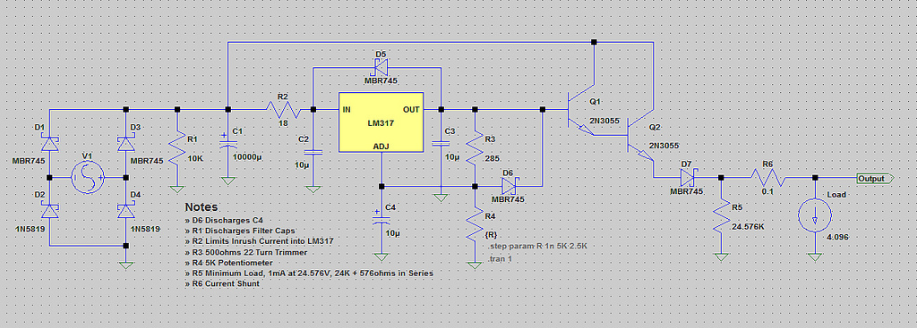
The voltage range will be from 0V to 24V, and the current is not expected to exceed 4A. A microcontroller and an LCD could potentially be added to measure voltage and current. The schematic appears to be generally acceptable....