
0-28 Volt 6A regulated variable power supply circuit with 7815 and two 2n3055

The described power supply circuit is a versatile solution for applications requiring adjustable voltage and current. The use of two 2N3055 transistors in a push-pull configuration enhances the output current capability, making it suitable for powering devices that demand higher current levels. The 7815 voltage regulator serves as a fundamental component for maintaining a stable output voltage under varying load conditions, while the fuses provide essential protection against overcurrent scenarios, ensuring the longevity and reliability of the power supply.
The rectification stage is crucial, as it converts the AC voltage from the transformer into a stable DC voltage. The calculated rectified voltage of approximately 42.30 volts necessitates the use of capacitors rated for at least 50 volts to prevent breakdown and ensure safe operation. The inclusion of diodes in the output stage not only aids in achieving the desired voltage range but also protects the transistors from potential damage due to excessive voltage.
The adjustable output voltage, facilitated by the potentiometer P1, allows users to fine-tune the voltage to meet specific requirements, making this power supply suitable for various electronic projects. The current limiting feature provided by potentiometer P2 is particularly beneficial in preventing damage to both the power supply and connected loads, as it allows users to set a safe operating current.
In summary, this power supply circuit is designed with both functionality and safety in mind, providing a robust solution for a wide range of electronic applications. The careful selection of components and design considerations ensures reliable operation, making it an excellent choice for hobbyists and professionals alike.This is definitely an simple to create power supply which has reliable, clear and regulator 0 to 28 Volt 6/8 Ampere output voltage. By using two 2N3055 transistor, you`ll get two times the amount of electric current. Although the 7815 power regulator is going to kick in on brief circuit, overload and thermal overheating, the fuses within the prima
ry section of the transformer and also the fuse F2 in the output will protected your power supply. The rectified voltage of: 30 volt x SQR2 = 30 x 1. 41 = 42. 30 volt measured on C1. So all capacitors ought to be rated at 50 volts. Caution: 42 volt is the voltage that might be around the output if one of the transistors ought to blow. P1 allows you to `regulate` the output voltage to anything between 0 and 28 volts. The LM317 lowest voltage is 1. 2 volt. To have a zero voltage around the output I`ve put 3 diodes D7, D8 and D9 on the output of the LM317 to the base of the 2N3055 transistors.
The LM317 optimum output voltage is 30 volts, but applying the diodes D7, D8 & D9 the output voltage is approx 30v - (3x 0. 6v) = 28. 2volt. P2 will certainly let you to set the limit of the optimum available electric current at the output +Vcc.
When using a 100 Ohm / 1 watt variable resistor the current is limited to approx. 3 Amps @ 47 Ohm and +- 1 Amp @ 100 Ohms. 🔗 External reference
Related Circuits

This circuit is powered by a 12-V DC power supply. The input to the circuit is amplified to generate a 10,000-V DC output. The output of the up-converter is subsequently directed into a 10-stage high-voltage multiplier to achieve a...
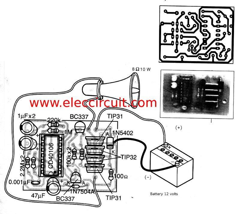
This is a simple siren sound generator with high power output and significant noise. The circuit utilizes digital ICs, specifically the CD4046, in an inverter configuration, along with four transistors to amplify the current output to a horn speaker...

This circuit utilizes three readily available 555 timer integrated circuits (ICs), all functioning as astable multivibrators. The first 555 timer has both an on period and an off period of 1 second. This IC regulates the on/off intervals of...
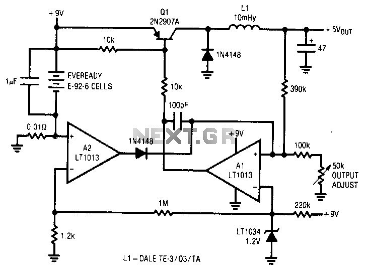
A simple battery-powered switching regulator provides 5 V output from a 9-V source with 80% efficiency and a 50 mA output capability. When Q1 is activated, its collector voltage increases, allowing current to flow through the inductor. This causes...
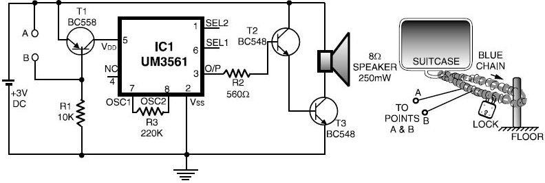
This luggage or bike alarm can be utilized while traveling by train or bus. Typically, luggage is secured using a chain-and-lock arrangement; however, there are still vulnerabilities. The luggage or bike alarm system is designed to enhance the security of...
The range of this FM transmitter is approximately 100 meters when powered by a 9V DC supply. The circuit consists of three stages. The first stage is a microphone preamplifier. The FM transmitter circuit is designed to convert audio signals...
Warning: include(partials/cookie-banner.php): Failed to open stream: Permission denied in /var/www/html/nextgr/view-circuit.php on line 713
Warning: include(): Failed opening 'partials/cookie-banner.php' for inclusion (include_path='.:/usr/share/php') in /var/www/html/nextgr/view-circuit.php on line 713