Medium-Power FM Transmitter
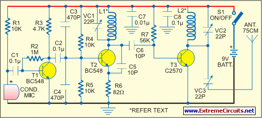
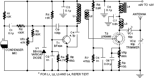
The range of this FM transmitter is approximately 100 meters when powered by a 9V DC supply. The circuit consists of three stages. The first stage is a microphone preamplifier.
The FM transmitter circuit is designed to convert audio signals from a microphone into frequency-modulated radio waves, which can then be transmitted over a distance of approximately 100 meters. The circuit operates with a 9V DC power supply, making it suitable for portable applications.
The first stage of the circuit is the microphone preamplifier. This stage is crucial for amplifying the weak audio signals picked up by the microphone. Typically, an operational amplifier (op-amp) is used in this configuration, providing the necessary gain to ensure that the audio signal is strong enough for subsequent processing. The preamplifier stage may also include passive components such as resistors and capacitors to filter out noise and stabilize the gain.
The second stage of the transmitter is the modulator. In this stage, the amplified audio signal is used to modulate a high-frequency carrier wave generated by an oscillator circuit. The oscillator is usually based on a crystal or LC circuit, which determines the frequency of the transmitted signal. The modulation process alters the amplitude or frequency of the carrier wave in accordance with the audio signal, allowing the information to be encoded onto the radio wave.
The third stage is the output stage, which typically includes a power amplifier. This stage boosts the power of the modulated signal to ensure that it can be transmitted effectively over the desired range. An antenna is connected to the output stage to radiate the modulated signal into the air. The design of the antenna is critical, as it must be matched to the frequency of the transmitter to maximize efficiency and range.
Overall, the FM transmitter circuit is a compact and efficient design that allows for the wireless transmission of audio signals over a short distance, making it ideal for various applications such as personal broadcasting or educational demonstrations. Proper attention to component selection and circuit layout is essential to achieve optimal performance and reliability in the final product.The range of this FM transmitter is around 100 meters at 9V DC supply. The circuit comprises three stages. The first stage is a microphone preamplifier bu.. 🔗 External reference

