
3170 IC For Telephone Remote Control Circuit
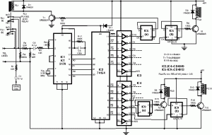
The teleremote circuit utilizes a telephone line as a medium for controlling electrical appliances from a distance. The primary components of this circuit include a telephone interface, a relay module, and the appliance to be controlled.
When a user makes a call to the designated telephone number associated with the teleremote circuit, the circuit detects the incoming call through the telephone interface. This is typically achieved using a hook switch or a dedicated telephone line interface IC. Upon detecting the call, the circuit may generate a signal to activate a relay, which is connected to the appliance.
The relay acts as a switch that can handle the high voltage and current required by household appliances. Depending on the design, the circuit may allow for toggling the state of the relay with either a single call or by detecting specific tones or DTMF (Dual-Tone Multi-Frequency) signals.
For enhanced functionality, the circuit can be designed to provide feedback to the user, such as an audible tone or a visual indicator (LED) to confirm that the appliance has been successfully turned on or off. Additionally, safety features may be incorporated to prevent unauthorized access or accidental activation of the appliance.
This type of circuit is particularly useful in home automation systems, allowing users to control appliances remotely without the need for specialized equipment beyond a standard telephone. The simplicity of utilizing existing telephone infrastructure makes it a cost-effective solution for remote control applications.This circuit bellow shows a teleremote circuit which enables switching ‘on and ‘off of appliances through telephone lines. Can be used .. 🔗 External reference
Related Circuits
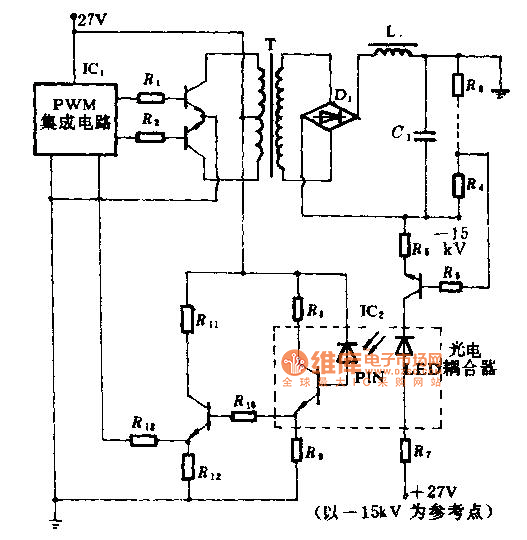
The technical parameters of high-speed optocouplers include a rise time (t1) of less than or equal to 300 ns, a circuit transfer ratio (CTR) of 50%, an isolation voltage (VSO) of at least 15,000 V, and an output transistor...

An ultra-simple circuit of the tilt sensor alarm can be fabricated using readily available, inexpensive components. The circuit operates as a true transistor-based design. The tilt sensor alarm circuit utilizes a tilt sensor, which is a device that detects the...

A simple circuit that can generate an inverted square wave similar to the one used by the inventor on his function generator. To construct a circuit that produces an inverted square wave, a basic approach involves using a 555 timer...

An active amplified transformer isolated signal splitter that enables a hum-free connection of one guitar to multiple amplifiers, while also providing a direct output. This includes a discussion on using audio transformers for equipment interconnections and mentions line-level transformers...
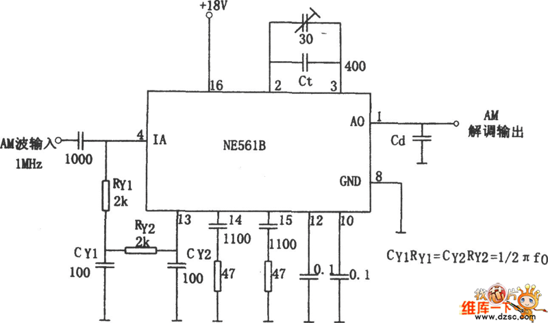
The figure illustrates a bilateral band modem circuit utilizing the NE561B component. The input modulating signal operates at a loading frequency of f0 = 1 MHz. When the AM modulation signal is applied to the input terminal of the...

Battery vampires are circuits designed to extract as much energy as possible from batteries or cells. They are not regulated drivers; rather, they are boost circuits that create a higher output voltage from a low input voltage and provide...