
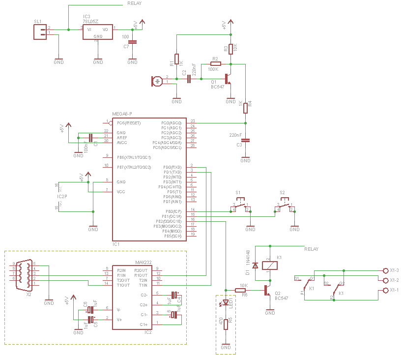
Electronic Gain Control in Quartz-Stabilized Oscillator

This circuit represents a quartz-stabilized oscillator featuring electronic gain control, which enhances the stability and precision of the output frequency. The utilization of a quartz crystal allows for high-frequency accuracy, making this oscillator suitable for various applications requiring stable signal generation.
In this design, the traditional filament lamp, often employed for amplitude stabilization, has been replaced with a more efficient electronic gain control mechanism. This substitution not only improves the reliability of the circuit but also reduces power consumption and increases the overall lifespan of the oscillator.
The circuit typically includes a quartz crystal oscillator, which sets the fundamental frequency, and an amplifier stage that provides the necessary gain. The electronic gain control is implemented using a variable resistor or a digital potentiometer, allowing for real-time adjustments to the amplitude of the output signal. Feedback loops are utilized to maintain the desired output level and to ensure that the oscillator remains stable under varying load conditions.
Power supply considerations are also crucial for the performance of this circuit. A regulated power supply is recommended to minimize noise and fluctuations that could affect the oscillator's stability. Additionally, decoupling capacitors should be placed close to the power pins of the active components to filter out high-frequency noise.
In summary, this quartz-stabilized oscillator circuit with electronic gain control offers a modern solution for generating stable frequencies with enhanced performance characteristics compared to traditional methods. Its design allows for flexibility in applications, making it suitable for communication systems, signal processing, and other electronic devices requiring precise frequency generation.This is a quartz-stabilized oscillator circuit with electronic gain control. Replacing the common filament lamp for amplitude stabilization, this circuit use.. 🔗 External reference
Related Circuits

This circuit is guaranteed to oscillate at a frequency of approximately 2.2/(R1 x C) if R2 is greater than R1. Additionally, the number of gates can be reduced further by replacing gates 1 and 2 with a non-inverting gate. The...
Utilizing a dual polarity power supply (+-5V is suitable) can resolve most clipping issues. It is necessary to consult the data sheet for the appropriate pins to connect the voltages. A dual polarity power supply is essential in many electronic...
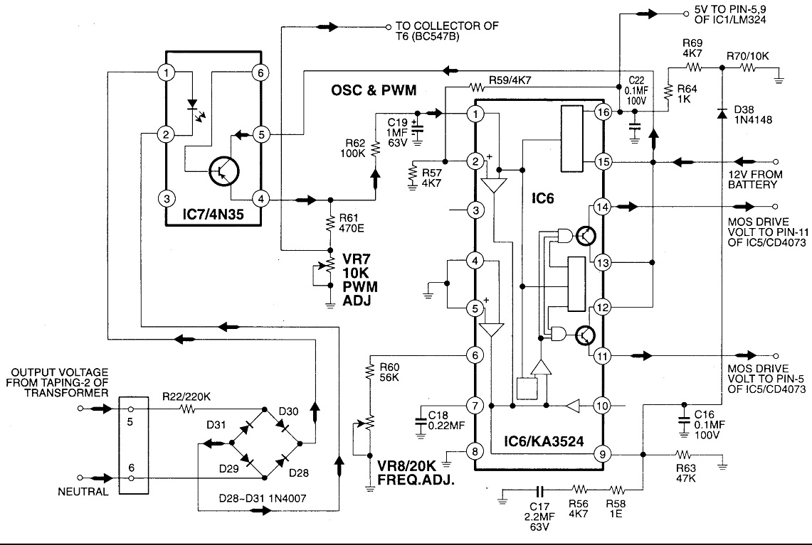
Circuit No. 1 (Oscillator Circuit and Feedback Circuit) Circuit No. 2 (MOS Driver Circuit) Final Product: - Operation of Circuit No. 1 (Oscillator Circuit and Feedback Circuit) This inverter utilizes Pulse Width Modulation (PWM) technology. The working principle of...
A 555 timer can be configured to simulate a multi-gang potentiometer by controlling the mark-space ratio. The switching rate should be at least twice the maximum expected signal frequency that the potentiometer has to handle. The 555 timer is an...
The TDC1808/TDC1809 is a pair of wireless remote control transmitter and receiver components. They utilize an internal antenna to transmit both digital and analog signals. These components are suitable for various wireless remote control devices. Key features include compact...
For those who prefer convenience, it is possible to turn the bedroom light on or off without leaving the bed simply by clapping hands. This concept inspired the design of a clap-activated light control system. Various clap switch projects...