
0-50v 2a Bench Power Supply

This variable power supply is engineered to meet the diverse needs of laboratory applications, offering flexibility in output voltage and current levels. The use of two integrated circuits allows for precise control over the power supply's performance characteristics.
The schematic typically includes a transformer to step down the AC mains voltage, followed by a rectifier circuit to convert the AC voltage to DC. The two ICs serve distinct roles: one IC may be responsible for voltage regulation, while the other manages current regulation. This dual-IC configuration ensures that the power supply can maintain stable output under varying load conditions.
Additional components such as capacitors are included to filter out noise and provide stability to the output voltage. Potentiometers may be integrated into the design to allow users to easily adjust the output voltage and current settings.
Protection features, such as fuses or circuit breakers, are also essential to safeguard both the power supply and connected devices from overcurrent or short-circuit conditions. Visual indicators, such as LED lights, can be incorporated to provide real-time feedback on the operational status of the power supply.
Overall, this variable power supply is a versatile tool for experimental setups, testing, and prototyping, catering to a wide range of electronic devices and circuits in laboratory environments.Variable power supply for laboratories. With two ICs can take different output voltage and amperage 🔗 External reference
Related Circuits
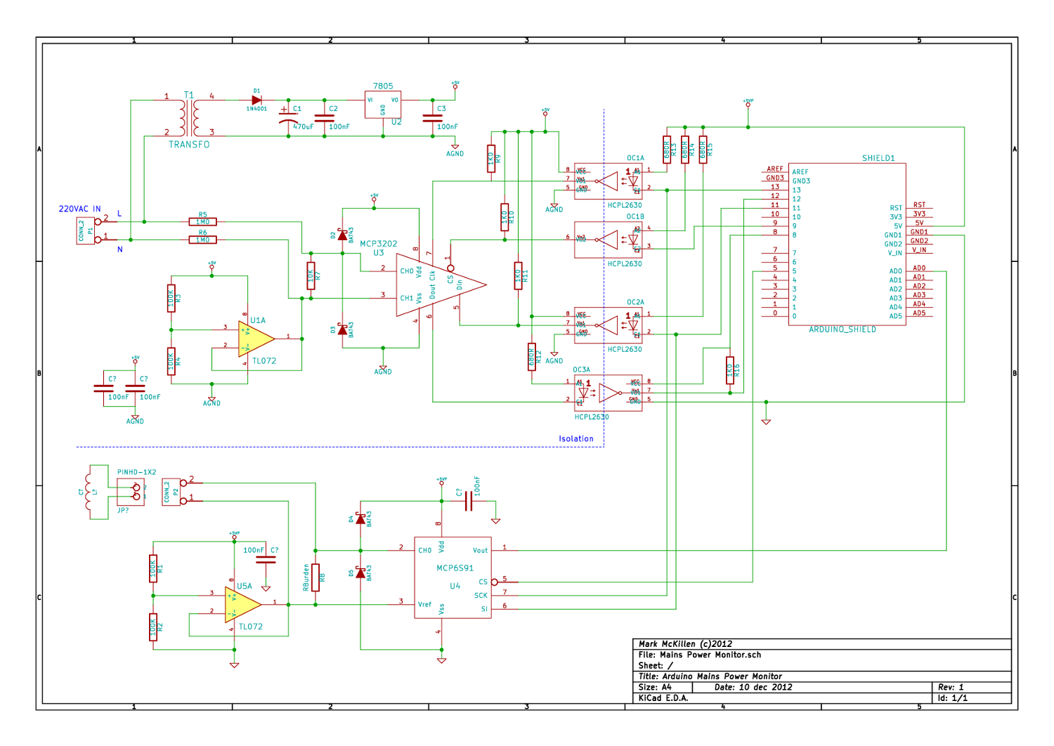
A mains (220-240VAC) power monitoring circuit has been sought for interfacing with an Arduino. While the OpenEnergyMonitor solution employs a transformer for isolation and measurement of mains voltage, it has been noted that the transformer does not couple effectively...
This is a simple circuit of a low-power voltage regulator reference. This circuit can produce a stable voltage reference. The low-power voltage regulator reference circuit is designed to provide a consistent output voltage, which is crucial for various electronic applications...
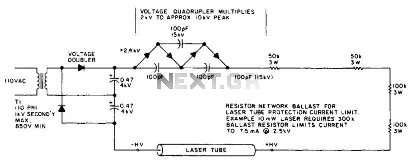
This circuit delivers a peak voltage of 10 kV, while limiting the current to 7.5 mA at 2 kV. The resistors included in the design serve the purpose of ballasting. Additionally, the starting circuit is unable to sustain the...
This is a simple NiCd battery charger powered by solar cells. A solar cell panel or an array of solar cells can charge a battery at more than 80% efficiency, provided the available voltage exceeds the fully charged battery...
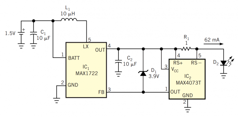
Although white LEDs are common in a variety of lighting applications, their 3 to 4V forward-voltage drop makes low-voltage applications challenging. Charge pumps and other ICs are available for driving white LEDs, but they generally don't work with the...
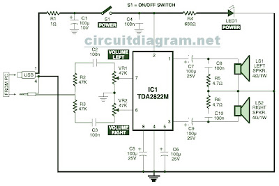
This is the circuit diagram of a USB-powered computer speaker, commonly referred to as multimedia speakers for PCs. The circuit features a single-chip design, operates on a low-voltage electrical power supply, is compatible with USB power from computers, includes...