
Solar-Powered High Efficiency Battery Charger
The described circuit operates as an efficient solar-powered charger for nickel-cadmium (NiCd) batteries, utilizing a solar cell array to convert solar energy into electrical energy. The efficiency of the charging process is notably high, exceeding 80%, which is achieved through careful management of voltage levels and the implementation of a step-down regulator. The presence of a diode between the solar array and the battery is essential, as it ensures that the voltage supplied to the battery exceeds its fully charged voltage by a small margin, accounting for the diode's forward voltage drop.
The MAX639 integrated circuit plays a pivotal role in this design, functioning in an unconventional manner by regulating the input voltage rather than the output voltage. This unique approach allows it to maintain optimal charging conditions by adjusting the current flow based on the solar array's output. The twelve amorphous solar cells, each with a minimum surface area of 100 cm², provide the necessary input voltage to the regulator, which in turn manages the charging of up to five NiCd cells in series.
The potential dividers R2/R3 and R1/R2+R3 are critical components in the circuit, as they control the feedback mechanisms that disable and enable the internal regulation loop and battery input sensing. This feedback system ensures that the charger can adapt to varying solar conditions, maintaining maximum power transfer to the batteries while preventing overcharging or undercharging scenarios.
Current limiting features within the MAX639 ensure that the output current does not exceed 200mA, thus protecting the battery from potential damage due to excessive charging currents. The internal switch of the regulator, which operates with a resistance of less than 1 ohm, further contributes to the efficiency of the circuit, allowing for significant power delivery while minimizing energy losses.
Overall, the combination of low quiescent current, high efficiency, and the ability to handle variable input voltages makes this solar charger design superior to traditional single-diode configurations, capable of delivering up to four times more power to the connected NiCd batteries. The inclusion of a 100-µH suppressor choke rated for 600mA ensures stability in the circuit, filtering out potential voltage spikes and providing a reliable charging solution.This is a simple NiCd battery charger powered by solar cells. A solar cell panel or an array of solar cells can charge a battery at more than 80 % efficiency provided the available voltage exceeds the fully charged` battery voltage by the drop across one diode, which is simply inserted between the solar cell array and the battery. Adding a step-do wn regulator enables a solar cell array to charge battery packs with various terminal voltages at optimum rates and with efficiencies approaching those of the regulator itself. However, the IC must then operate in an unorthodox fashion (a. k. a. Elektor mode`) regulating the flow of charge current in such a way that the solar array output voltage remains near the level required for peak power transfer.
Here, the MAX639 regulates its input voltage instead of its output voltage as is more customary (but less interesting). The input voltage is supplied by twelve amorphous solar cells with a minimum surface area of 100 cm2.
Returning to the circuit, potential divider R2/R3 disables the internal regulating loop by holding the V-FB (voltage feedback) terminal low, while divider R1/R2+R3 enables LBI (low battery input) to sense a decrease in the solar array output voltage. The resulting deviation from the solar cells` peak output power causes LBO (low battery output) to pull SHDN (shutdown) low and consequently disable the chip.
LBI then senses a rising input voltage, LBO goes high and the pulsating control maintains maximum power transfer to the NiCd cells. Current limiting inside the MAX639 creates a ceiling` of 200mA for I out. Up to five NiCd cells may be connected in series to the charger output. When on` the regulator chip passes current from pin 6 to pin 5 through an internal switch representing a resistance of less than 1 ohm.
Benefiting from the regulator`s low quiescent current (10 microamps typical) and high efficiency (85 %), the circuit can deliver four times more power than the single-diode configuration usually found in simple solar chargers. Coil L1 is a 100- µH suppressor choke rated for 600mA. 🔗 External reference
Related Circuits
Typically, a charged lead-acid battery and a power inverter are utilized to ensure a well-organized holiday where family members can enjoy their electric and electronic devices. With rechargeable lead-acid batteries, it is often beneficial, if not essential, to determine...
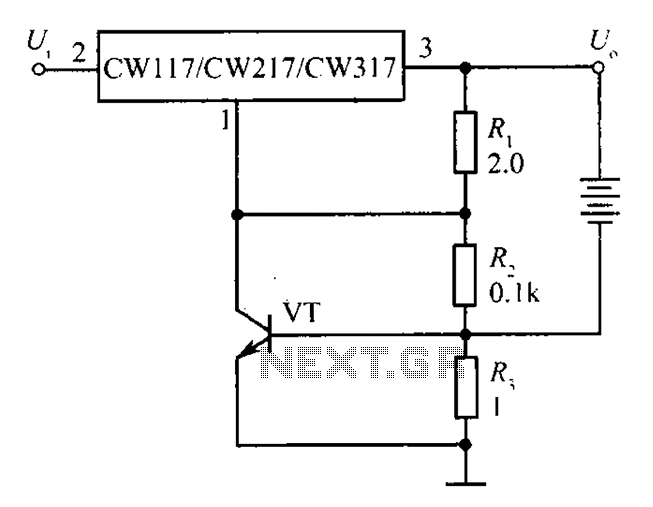
The circuit depicted in the figure is a limiting protection charger. The VT transistors and resistor R3 create a limiting network. As illustrated, resistor R3 is connected in series with the battery being charged, acting as the emitter resistor...

This circuit performs a rapid battery test without requiring a power supply or costly moving-coil voltmeters. It features two ranges: when SW1 is configured as depicted in the circuit diagram, the device can test batteries ranging from 3V to...
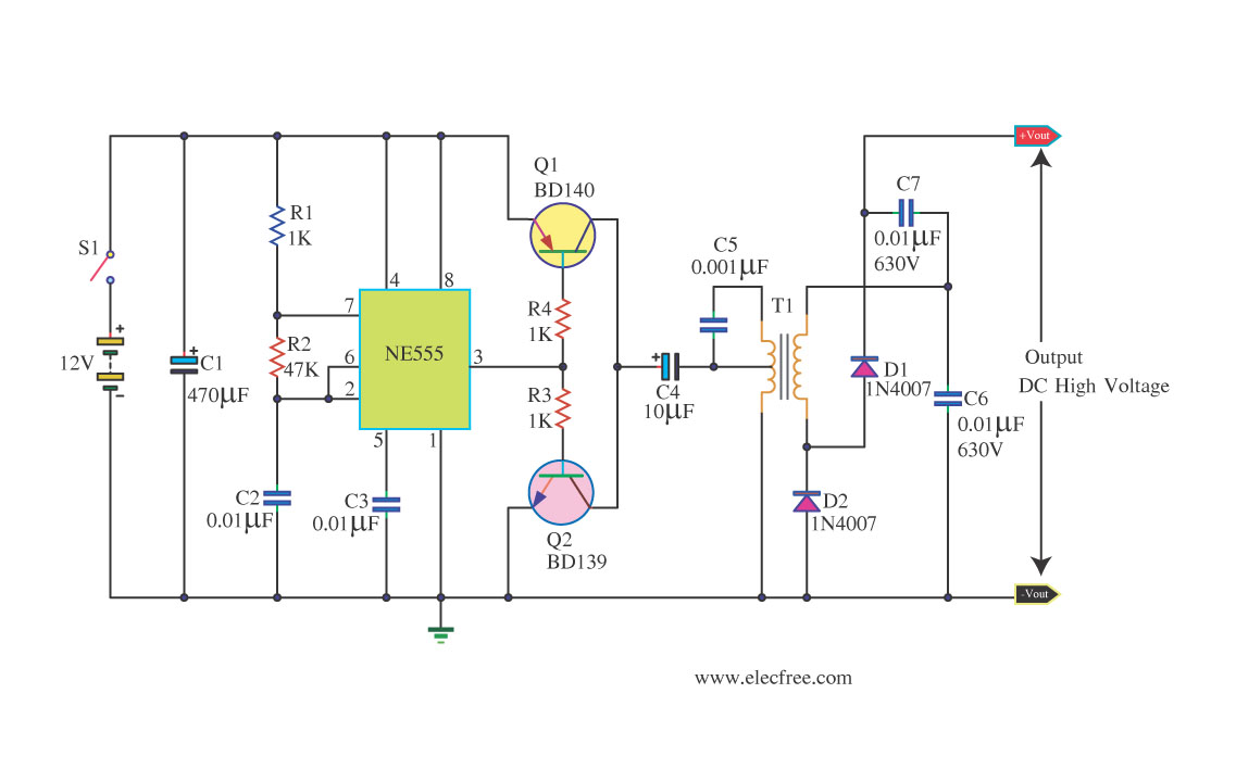
This circuit is a DC to DC inverter that can convert a 12V DC battery voltage to a high voltage of 300V DC. This circuit operates with low current. This DC to DC inverter circuit is designed to efficiently step...
The new version has PCBs available and is recommended for optimal sound quality. For those needing tone controls, Project 97 is an excellent choice, offering superior sound quality and tone control features. While preamps have been widely discussed, they...
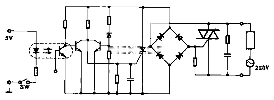
This application example illustrates a photovoltaic control circuit. In this circuit, the Triac functions as a solid-state relay, providing an AC power supply path to the load. It is designed to achieve high current control signals using a small...
Warning: include(partials/cookie-banner.php): Failed to open stream: Permission denied in /var/www/html/nextgr/view-circuit.php on line 713
Warning: include(): Failed opening 'partials/cookie-banner.php' for inclusion (include_path='.:/usr/share/php') in /var/www/html/nextgr/view-circuit.php on line 713