
0 to 360 phase shifter

The described phase shifter circuit operates by utilizing two stages of phase shift, where each stage is capable of providing a shift of 0° to 180°. The stages are interconnected, allowing for the cumulative effect of the phase shifts to reach a full 360°. This feature is particularly useful in applications requiring precise phase control, such as in signal processing, modulation, and synchronization tasks.
The circuit is powered by both AC and DC supplies, which enhances its versatility and allows it to be integrated into various electronic systems. The model designation L12884 indicates its specific design and functionality, making it easier for engineers to reference and implement in their projects.
The 2N3070 JFETs serve a critical role in this circuit by maintaining the integrity of the phase shift networks. Their high input impedance ensures that the phase shift networks are not loaded down, which could otherwise distort the phase shift characteristics. This characteristic of the JFETs is essential for achieving accurate and reliable phase shifting across the entire range.
Overall, this phase shifter circuit provides a robust solution for applications requiring adjustable phase control, with the added benefit of not compromising the performance of the phase shift networks through loading effects.Each stage provides 0° to 180° phase shift. By ganging the two stages, 0° to 360° phase shift is achieved This circuit is under:, power supplies, ac dc dc dc, 0° To 360° phase shifter l12884. By ganging the two stages, 0° to 360° phase shift is achieved The 2N3070 JFETs do not load the phase shift networks.
The 2N3070 JFETs do not load the phase shift networks.
Related Circuits
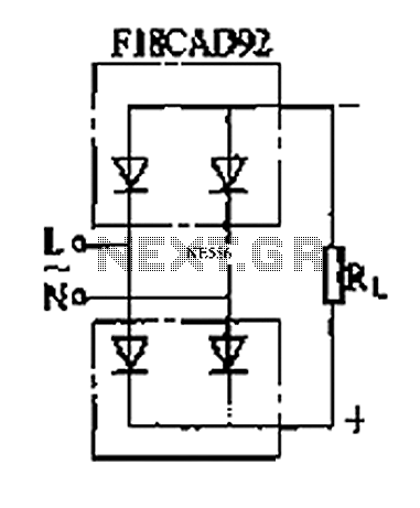
The circuit depicted is a single-phase bridge rectifier. It consists of arms with a cathode (negative electrode) and parallel anodes (positive electrodes) arranged in a configuration that connects multiple rectifier modules to form a bridge, commonly referred to as...
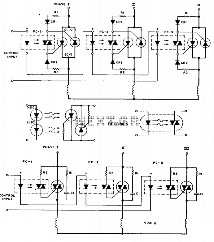
To simplify the following schematics and facilitate easy understanding of the principles involved, the following schematic substitution is used. Note that the triac driver is of limited use at 3-phase voltage levels. The following are three-phase switches for low...
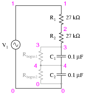
Construct the circuit and measure the voltage drops across each component using an AC voltmeter. Additionally, measure the total (supply) voltage with the same voltmeter. It will be observed that the individual voltage drops do not sum up to...
NJM2268 is a dual video 6dB amplifier designed for S-VHS VCRs, high-bandwidth VCRs, and similar applications. One channel features a clamp function that stabilizes the DC level of the video signal, while the other channel operates as a bias...
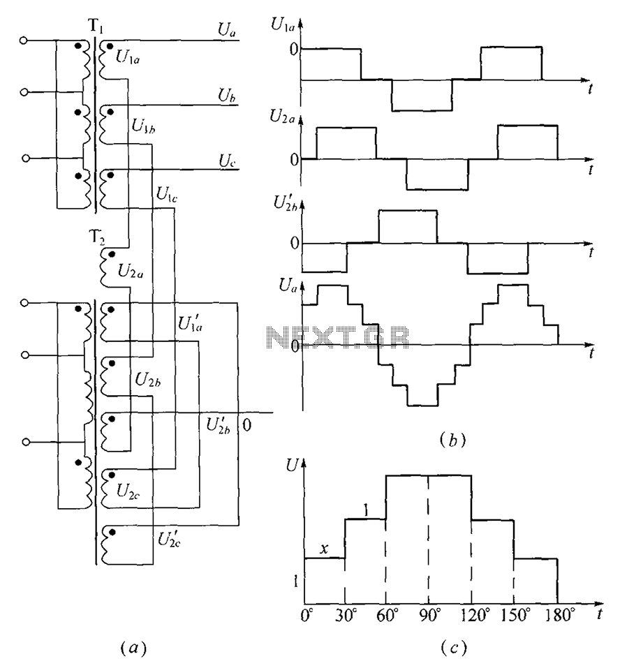
As shown, (a) for the three-phase step wave inverter output transformer winding connections; (b) in the figure, its output waveform. The three-phase step wave inverter is designed to convert direct current (DC) into a three-phase alternating current (AC) output. This...
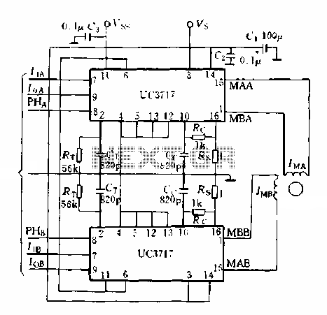
A typical application of a two-phase stepper motor is illustrated in Figure 5-15. It consists of two UC3717A components that can create a microcomputer control system for a two-phase permanent magnet or hybrid stepping motor. The control signals for...