
Three-phase switch

The described circuit involves a three-phase switching system designed for low-voltage applications. The schematic substitution mentioned is aimed at enhancing clarity and understanding of the operational principles behind the circuit. The triac driver serves as a key component in this setup; however, it is important to recognize its limitations when dealing with 3-phase voltage levels, as it may not perform optimally under such conditions.
In this context, three-phase switches are employed to manage the flow of electrical power across three separate phases, which is a common requirement in industrial and commercial power distribution systems. The use of low-voltage switching enhances safety and efficiency in managing electrical loads.
For applications requiring higher current handling, the circuit can be modified to incorporate inverse parallel silicon-controlled rectifiers (SCRs). These SCRs can be triggered in a manner that allows for greater control over the power delivered to the load. The inverse parallel configuration allows for bidirectional current flow, which is essential for AC applications. Each SCR is triggered at specific intervals to maintain the desired phase control and ensure optimal performance of the circuit.
The overall design of the circuit should include appropriate protection mechanisms, such as fuses or circuit breakers, to safeguard against overcurrent conditions. Additionally, proper heat dissipation measures must be considered, especially when utilizing SCRs, as they can generate significant heat during operation. The layout should also ensure minimal electromagnetic interference (EMI) and incorporate adequate filtering to maintain signal integrity across the switching components.
In conclusion, the schematic serves as a foundational tool for understanding the operation of three-phase low-voltage switches, while also providing pathways for scaling up to higher current capabilities through the integration of SCRs. Proper implementation of these components will result in an efficient and reliable three-phase power management system. To simplify the following schematics and facilitate easy understanding of the principles involved, the following schematic substitution is used (Note the triac driver is of limited use at 3 f voltage levels). The following are three-phase switches for low voltage. Higher currents can be obtained by using inverse parallel SCRs which would be triggered as shown.
Related Circuits
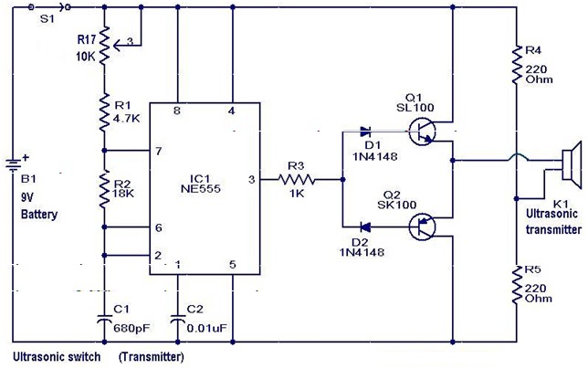
A new type of remote control operates based on ultrasonic sound. The transmitter section of the circuit is constructed around IC1 (NE 555), configured as an astable multivibrator functioning at 40 kHz. The output from IC1 is amplified by...
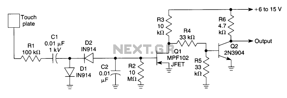
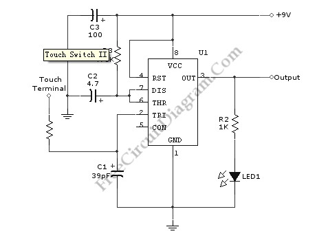
When the touch plate is activated by a large object, such as a human body, stray 60 Hz pickup is rectified by diodes D1 and D2, resulting in a negative voltage across resistor R2 and capacitor C2, which affects...
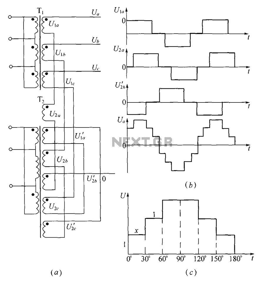
As shown, (a) for the three-phase step wave inverter output transformer winding connections; (b) in the figure, its output waveform. The three-phase step wave inverter is designed to convert direct current (DC) into a three-phase alternating current (AC) output. This...
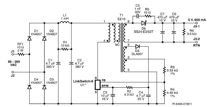
A simple 3.25W constant voltage/constant current (CV/CC) charger can be designed using the LinKSwitch family IC manufactured by Power Integrations. This electronic circuit project is intended to provide a 5-volt output with a maximum current of 650mA. The 3.25W...
Utilizing the specified values depicted in the schematic diagram, this circuit features a timed ON period of 4 seconds. The ON time is governed by the values of capacitor C2 and resistor R3; increasing either C2 or R3 will...
This circuit, based on the NE555 timer IC, toggles the output on and off using a momentary switch. It functions similarly to a mechanical latching relay but resets to its initial state when the power supply is turned off....