
00 to 99 minute timer using PIC16F628A microcontroller

The digital timer circuit is designed around the PIC16F628A microcontroller, which is a popular choice for embedded applications due to its versatility and ease of use. The microcontroller's I/O pins are configured to interface with the LCD and tact switches, allowing for seamless user interaction. The HD44780 LCD is a widely utilized display module that provides a straightforward means of displaying alphanumeric characters, making it ideal for timer applications.
The tact switches connected to the RB0, RB1, and RB2 pins are utilized for controlling the timer. The RB0 pin acts as the Start/Stop control, while the RB1 and RB2 pins are designated for setting the unit and ten-minute values, respectively. The microcontroller's firmware processes the inputs from these switches, updating the timer settings accordingly.
The logic high signal from the RA3 pin is pivotal for controlling external devices such as relays or LEDs. In this implementation, an LED is used to provide a visual indication of the timer's status. When the timer is activated, the RA3 pin outputs a high signal, illuminating the LED to signify that the countdown is in progress. Upon completion of the timer duration, the LED is turned OFF, providing a clear indication to the user that the set time has elapsed.
The initialization routine for the LCD display is crucial for providing feedback to the user. Upon powering the device, the microcontroller initializes the display and provides a clear message indicating that the timer is OFF. This feedback is essential for user confidence in the operation of the timer.
The time setting mechanism is designed for simplicity, allowing users to increment the timer values easily. The use of the mikroC Pro for PIC compiler streamlines the development process, enabling the implementation of the Delay_ms() function to create timing delays without the complexity of hardware timer configurations. This approach ensures that the timer operates accurately while maintaining a straightforward design.
In summary, this PIC-based digital timer project showcases the integration of a microcontroller, LCD display, and user input through tact switches, resulting in a functional and user-friendly timer application. The design emphasizes simplicity and clarity, making it an excellent example for educational purposes and practical applications in embedded systems.A source code for a very simple PIC based digital timer. The actual hardware of the project isn`t with me anymore. I will rather demonstrate it using my DIY PIC16F628A breadboard module and I/O board. The complete circuit diagram along with the firmware developed using mikroC Pro for PIC compiler is provided in the article. As I mentioned earlier, the microcontroller used in this project is PIC16F628A running at 4. 0 MHz clock using an external crystal. An HD44780 based 16G—2 character LCD is the main display unit of the project where you can watch and set the timer duration using tact switch inputs. There are three tact switches connected to RB0 (Start/Stop), RB1 (Unit), and RB2 (Ten) pins. You can select the timer interval from 0-99 min using Unit and Ten minute switches. The Start/Stop switch is for toggling the timer ON and OFF. When the timer gets ON, a logic high signal appears on the RA3 pin, which can be used to switch on a Relay.
The circuit diagram of this project is described below. I am using my self-made breadboard module for PIC16F628A and experimenter`s I/O board here to demonstrate this project. Since there is no relay switch in the I/O board, I am connecting the timer output (pin RA3) to an LED.
When the timer starts, the LED is turned ON. As the timer duration is elapsed, the LED is turned OFF. When the device is powered ON, the microcontroller initializes the LCD display and shows the following message. The timer is initially OFF and so does the LED or relay, whichever is connected to RA3 pin. You can set time duration between 00-99 min (in step of 1 min) using the Unit and Ten tact switches. Each switch press will increment the corresponding time digit. When the desired time is set, press the Start/Stop switch to turn ON the timer. The RA3 pin goes high (LED glows) and the count down begins. When the timer is ON, the remaining time is also shown on the LCD screen. When the time elapsed, the timer stops and the LED turns OFF. You can interrupt and stop the timer at anytime by pressing the Start/Stop switch once more. The firmware for PIC is developed using mikroC Pro for PIC compiler. The use of Timers are avoided for simplicity. The time delays are created using the Delay_ms() function of mikroC, which seems to give reasonably accurate timing delays.
🔗 External reference
Related Circuits
System Oscillator Crystal/Ceramic Oscillator. The following circuit combination of resistors, capacitors, and inductors depicts an equivalent circuit for a crystal or ceramic oscillator. The system oscillator, specifically a crystal or ceramic oscillator, utilizes a combination of passive components, including resistors,...
Integrated AF power amplifiers have experienced significant advancements in recent years, offering enhanced power and ease of use. The TDA1519C from Philips features two power amplifiers that provide 11 W per channel in stereo mode or 22 W in...
The 8051 controller is mask-programmable, meaning it is programmed during manufacturing and cannot be reprogrammed afterward. However, the AT89C51 microcontroller, a derivative of the 8051, is reprogrammable. This device includes a timer, a serial port interface, and interrupt control,...
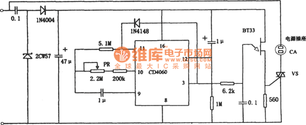
The figure illustrates a preset outage timer circuit designed for an electric cooker. The timing range of the circuit extends from 1 hour to 12 hours, adjustable via a potentiometer (PR). The timing mode operates on a counting basis,...
A teleremote circuit enables the switching on and off of appliances through telephone lines. It can be used to control appliances from any distance, overcoming the limited range of infrared and radio remote controls. The circuit can switch up...
The following circuit illustrates a Cat and Dog Repellent Timer Circuit Diagram. Features include the capability to maintain a deep cycle battery charged by a solar panel. The Cat and Dog Repellent Timer Circuit is designed to provide a humane...