
Help me Understand this Circuit Schematic
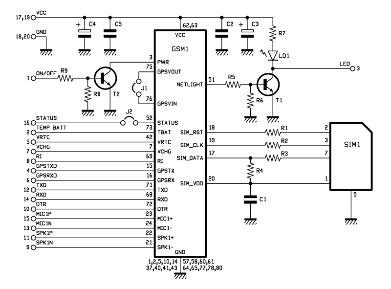
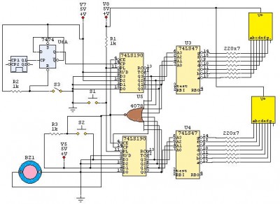
Capacitors are essential components in electronic circuits, serving various purposes, including energy storage, signal smoothing, and filtering. Capacitors C1, C4, and C5, specifically, are likely positioned on the power rail to mitigate voltage fluctuations and transient spikes, which can lead to unstable operation of the circuit. By providing a reservoir of charge, these capacitors help maintain a steady voltage level, thus enhancing the reliability of the circuit's performance.
The current ripple, which is the variation in the DC voltage level, can adversely affect the operation of sensitive components. When connected to an oscilloscope, the effect of these capacitors can be visualized, demonstrating their importance in maintaining signal integrity. A well-designed circuit will include these capacitors to ensure that power supply variations do not propagate through the circuit, potentially causing erratic behavior.
Resistors R6 and R8 play a critical role in controlling the operation of the transistors. By connecting these resistors to the bases of the transistors, they ensure that when the control signal is removed, the transistors do not remain in an active state. Instead, the resistors provide a path to ground that quickly discharges the base-emitter capacitance, allowing the transistors to turn off rapidly. This rapid switching is crucial for high-speed applications, where delays in turning off can lead to increased power consumption and reduced efficiency.
In summary, the combination of capacitors and resistors in this circuit design is vital for ensuring stable operation and efficient control of the transistors, contributing to the overall performance and reliability of the electronic system.Why do I need C1 What does it do I don`t understand their role in the circuit. Why do I need C4 and C5 I don`t understand their role in the circuit c) why doe I need R6 and R8. As for those caps on the power rail, they clean up the signal to make it less choppy so to speak(removing current ripple) you would see this with an osciliscope. The resistors on the bases of transistors to ground, make sure the the transistors turn off, by effectively removing power to them quickly by draining to ground so the circuit operates quickly. Ask-a-doc Web sites: If you`ve got a quick question, you can try to get an answer from sites that say they have various specialists on hand to give quick answers.
Justanswer. com. Traffic on JustAnswer rose 14 percent. and had nearly 400, 000 page views in 30 days. inquiries related to stress, high blood pressure, drinking and heart pain jumped 33 percent. I`m screaming your praises! WOW! I plugged my TV in and bammo! The picture came on bright and beautiful. What a relief! YOU saved me some money and headache. VM United States I`m screaming your praises! WOW! I plugged my TV in and bammo! The picture came on bright and beautiful. What a relief! YOU saved me some money and headache. VM United States I love this site! $9 instead of a repairman or new/used frig can`t be beaten. This older woman will worry less now that she knows about this site. Bless you all. Windy USA Wonderful service, prompt, efficient, and accurate. Couldn`t have asked for more. I cannot thank you enough for your help. Mary C. Freshfield, Liverpool, UK This expert is wonderful. They truly know what they are talking about, and they actually care about you. They really helped put my nerves at ease. Thank you so much! Alex Los Angeles, CA Thank you for all your help. It is nice to know that this service is here for people like myself, who need answers fast and are not sure who to consult. GP Hesperia, CA Just let me say that this encounter has been entirely professional and most helpful. I liked that I could ask additional questions and get answered in a very short turn around. Esther Woodstock, NY 🔗 External reference
Related Circuits
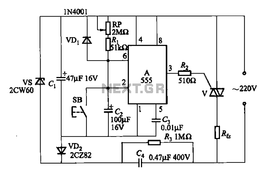
A 555 four-base integrated circuit delay circuit is designed to facilitate a transition from high to low output. When the button SB is pressed, the output is set to high, and after a specified delay, the output transitions to...
The industrial fuel oil furnace controller circuit consists of a power supply circuit, a testing and ignition control circuit, and a control implementation circuit, as illustrated in the accompanying diagram. The power supply circuit includes a step-down capacitor (C6),...
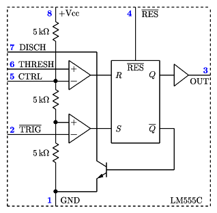
It is a typical Astable Multivibrator (AMV) setup. The capacitor charges through both resistors until it reaches 2/3 of Vcc, which is the level of the internal comparator. This triggers a flip-flop, activating the Discharge output (DIS). The capacitor...
This is a 24-second countdown timer circuit designed for automatic control of electronic loads. The timer circuit utilizes fast 74LS Schottky integrated circuits (ICs). A 24-second countdown begins when switch S3 is off and switch S2 is pressed. Switch...
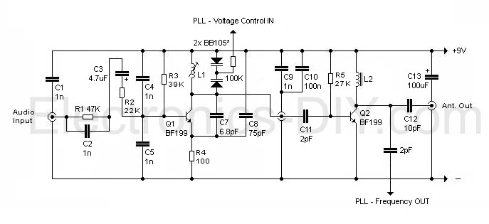
This circuit appears intriguing, and there is an intention to simulate and construct it; however, clarification is needed regarding the meaning of the three symbols in the circuit (one for audio input, one in the middle, and one at...
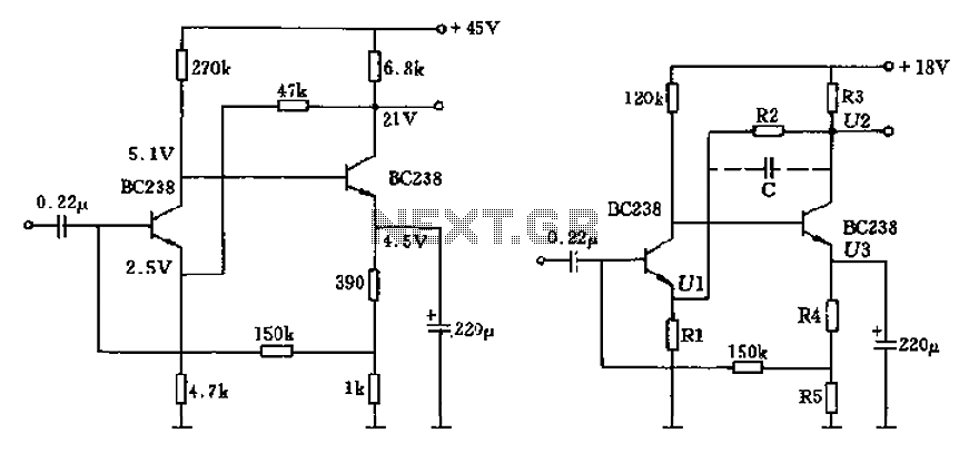
The circuit characteristic involves the elimination of external input resistors, which reduces the influence on the stabilization of the working point. It also employs two DC negative feedback loops. Additionally, the output from the second stage connects to the...