
1.2GHz Voltage Controlled Oscillator With Linear Modulation
The MAX2754 VCO is designed to provide a compact solution for generating high-frequency signals, making it suitable for various RF applications. The TUNE input enables precise frequency adjustments, allowing designers to tailor the oscillator's output to specific requirements. The modulation capabilities via the MOD input facilitate the integration of the VCO into communication systems where frequency shift keying (FSK) is employed.
In practical applications, the use of a potentiometer for the TUNE input allows for manual tuning, which can be beneficial during the initial setup or testing phases. The recommended resistor values (R1 to R4) for the data signal conditioning ensure that the modulation input receives a properly biased signal, optimizing the performance of the VCO in a digital communication context. The transfer slope of 500 kHz/V indicates that for every volt applied to the MOD input, the output frequency will shift by 500 kHz, providing a clear relationship between the input control voltage and the frequency deviation.
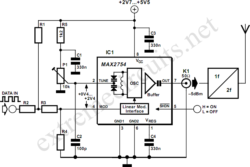
Overall, the MAX2754's features, including low power consumption, wide frequency range, and versatile modulation capabilities, make it a valuable component for engineers designing RF circuits, particularly in applications requiring precise frequency control and modulation.Since high frequency voltage-controlled oscillators, or VCOs, are not easy to construct, Maxim ( has produced an integrated 1. 2GHz oscillator, the MAX2754. The center frequency is set using the TUNE input, and a linear modulation input allows the frequency to be modulated.
The IC is available in an 8-pin µMAX package, operates from a supply of be tween 2. 7 V and 5. 5 V, and draws a current of less than 2 mA. Both TUNE and MOD operate over control voltage range of +0. 4 V to +2. 4 V. TUNE allows the VCO frequency to be adjusted from 1050 MHz to 1270 MHz. In some applications a PLL control voltage will be applied here, allowing the center frequency to be set exactly to a desired value. For simplicity in the circuit diagram we have shown a potentiometer. The MOD input allows the VCO to be modulated in a digital or analogue fashion, with a transfer slope of 500 kHz/V.
In the circuit we have shown an example where MOD is used for frequency shift keying (FSK) modulation. Resistors R1 to R4 shift the level of the data signal so that it has a center value of +1. 4 V and an amplitude corresponding to the desired frequency deviation. One example set of values, suitable for use with a 5 V power supply, is as follows: R1 = 480 , R2 = 100 , R3 = 220 und R4 = 270 .
🔗 External reference
Related Circuits
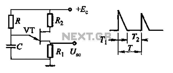
Common non-sinusoidal oscillator circuit, waveform and frequency formula - pulse wave oscillator - blocking oscillator transformer The common non-sinusoidal oscillator circuit is designed to generate pulse waveforms, which are characterized by their square or rectangular shape. These oscillators are...
A sine wave oscillator can be implemented using a Wien-Bridge oscillator, similar to the previous sine wave oscillator circuit; however, another method is now presented. The Wien-Bridge oscillator is a type of electronic oscillator that generates sine waves. It is...
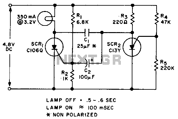
Applying voltage to the circuit triggers SCR1. With SCR1 on, the voltage on the anode of SCR2 rises until SCR2 triggers to commutate SCR1. The voltage on the gate of SCR1 will swing negative at this time, and only...
The motion games on the Nokia 5800 sparked an interest in creating a real-world version of a racing car controlled by tilting a phone. The motion-controlled robot, named Hercules due to its high torque and speed, is operated via...
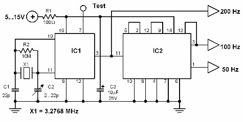
This circuit generates a 50 Hz timebase signal that is independent of the power line frequency. It is designed to provide the 50 Hz signal for electronic circuits that operate specifically with this clock frequency, primarily for circuits and...
Online Electronics Course covering the Science of Radio Frequency Engineering, including topics such as Electronics, Microwave Technology, Waveguides, Antennas, Tubes, Historical Context, Klystrons, Magnetrons, Traveling Wave Tubes (TWT), Internet of Things (IoT), Klystrodes, Broadcast Equipment, and Repair Techniques. The online...
Warning: include(partials/cookie-banner.php): Failed to open stream: Permission denied in /var/www/html/nextgr/view-circuit.php on line 713
Warning: include(): Failed opening 'partials/cookie-banner.php' for inclusion (include_path='.:/usr/share/php') in /var/www/html/nextgr/view-circuit.php on line 713